


Motorizable
Pedestal Ground
Mount Assembly
Step 1
Step 2
Step 3
Step 4
22
Installation Procedures
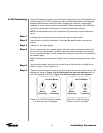
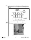
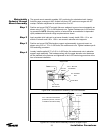
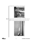
The ground mount assembly enables 180° positioning for selected azimuth viewing.
Azimuth range coverage is ±90° divided into three 120° continuous ranges with 30°
overlap. Elevation adjustment is continuous from 0 to 90°.
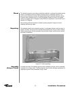
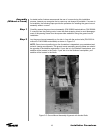
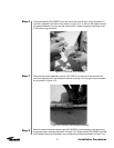
Position and mount 204737 azimuth tiller arm weldment to ground mount assembly as
shown using 0.75 x 1.75 in. A-325 bolts and nuts. Tighten hardware per A-325 tension-
ing procedure. NOTE: Mounting position of azimuth tiller arm weldment is dependent
upon predetermined azimuth range requirements as shown.
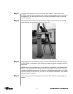
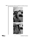
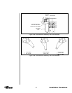
Apply supplied stick lubricant to set screw threads. Loosely install 0.50 x 1.0 in. set
screws in azimuth and 0.50 x 1.50 in. set screws in elevation strut supports.
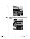
Position and mount 204754 elevation support angle assembly to ground mount as
shown using 0.50 x 1.75 in. A-325 bolts, flat washers and nuts. Tighten hardware per A-
325 tensioning procedure.
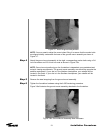
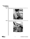
Loosely install supplied 0.75 x 2.00 in. A-325 bolts, flat washers and nuts in elevation
support angle assembly. This hardware along with the upper elevation strut hardware
will be attached to the antenna and tightened to the A-325 tensioning procedure at the
time of antenna installation.
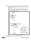
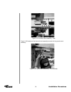
Support Plate
1/2 x 1” Bolt and
Flat Washer
3/4” Threaded
Rod
3/4” Flat
Washer
Pivot Block
3/4 x 1-3/4”
Bolt and Nut
EL SPT Angle
Assembly
AZ Tiller Arm
Weldment
3/4 x 2” Bolt and Flat Washer
(2 Washers per Bolt, one each
on Reflector and Mount Side)
Figure 3-8b: Ground Mount Assembly Tiller Arm Hardware
Figure 3-8c: Ground Mount Assembly Elevation Support Angle