


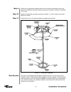

Subreflector
Adjustment
77
Operation
After the satellite has been acquired and testing has taken place with the spectrum analyzer,
the subreflector may need to be adjusted to maximize optimum performance of your anten-
na. The following procedures should be followed if a subreflector adjustment is required to
maximize optimum performance.
NOTE: All INTELSAT Type Approved antennas do not require subreflector adjustment. Using
the provided setting bar and procedures will correctly place the subreflector.
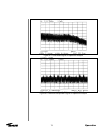
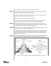
Before proceeding, azimuth and elevation patterns should be conducted to determine the
adjustments that need to be made. The goal is to achieve a high peak on the main lobe and
even distances between the main lobe and sidelobes as shown in Figure 4-6.
NOTE: No adjustments should be made in the receive band.
If your pattern dictates a need to adjust the azimuth angle(the left sidelobe requires adjust-
ment), the west side of the subreflector should be adjusted outward by loosening the screws
on the subreflector and adjusting the left side outward. An easy way to remember this
adjustment feature is through the acronym WOLD (West Out Left Down).
If your pattern dictates a need to adjust the elevation angle(the right sidelobe requires adjust-
ment), the bottom side of the subreflector should be adjusted downward by loosening the
screws between the subreflector and the struts and adjusting the bottom side of the subre-
flector downward. An easy way to remember this adjustment is through the acronym BOLD
(Bold Out Left Down).
Each of these adjustments should be repeated until each sidelobe is of equal distance from
the peak of the mainlobe.
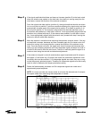
After the BOLD and WOLD adjustments have been made, it may be necessary to adjust the
main lobe. The goal is to achieve a high null depth (distance between lower intersection of
sidelobes and top of main lobe) as shown in Figure 4-6.
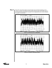
In order to adjust the main lobe pattern characteristics ALL subreflector adjustment screws
should be adjusted at the same degree (Note: Because the azimuth and elevation adjust-
ments have been set, it is very important that the null depth adjustment be carefully conduct-
ed. Be careful not to alter any previous adjustments that have been made to the subreflector.
Follow the procedure listed below when adjusting the null depth of the main lobe.
C-band feeds - Adjustment screws are 3/4 X 10. Move 1 turn per 1dB of imbalance.
Ku-band feeds - Adjustment screws are 1/4 X 20. Move 1 turn per 1 dB of imbalance.
All adjustments should be continued until the desired pattern is achieved. Upon completion
the antenna should be properly aligned with the satellite for maximum performance.