


71
6
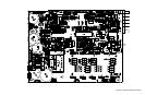
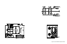
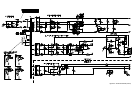
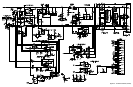
Diagrams
Introduction
This chapter contains drawings and diagrams for troubleshooting and maintaining the Agilent Model 66332A
Dynamic Measurement DC Source and the Agilent Model 66332A/6632B/6633B/6634B System DC Power
Supplies. Unless otherwise specified in the drawings, a drawing or diagram applies to all models and input voltage
options.
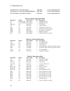
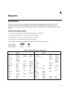
General Schematic Notes
a Components marked with an asterisk are model dependent (See Table 6-1).
a All resistors are in ohms 1%, 1/8 W, unless otherwise specified.
a All resistors are in ohms 1%, 1/8 W, unless otherwise specified.
a All capacitors are in microfarads unless otherwise specified.
a Unless otherwise noted, bias connections to integrated-circuit packages are as follows:
Common 5 V
14-pin packages pin 7 pin 14
16-pin packages pin 8 pin 16
20-pin packages pin 10 pin 20
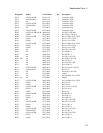
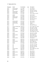
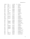
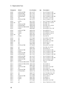
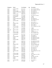
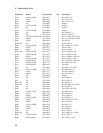
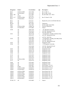
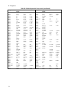
Table 6-1. Model-dependent Components
Designator 66332A/
6632B
6633B 6634B Designator 66332A/
6632B
6633B 6634B
C300, 304, 307 0.047 uF C411 2.2 uF 2.2 uF
C302 18000 uF 2200 uF 1200 uF C420, 421 0.022 uF 0.022 uF
C313 33,000 uF 18000 uF 8200 uF C422, 424, 425 1000 pF 220 pF
C314-316 0.047 uF C423 0.047 uF 0.0047 uF
C331, 332 2200 pF C425 1000 pF 1000 pF
C333 0.033 uF C426 0.1 uF
C335 3300 pF 3300 pF 0.047 pF C427 4700 pF
C340 0.01 uF C428-430 0.047 uF 0.047 uF
C344, 346 0.047 uF 0.022 uF 0.022 uF C431, 432 0.22 uF
C349, 352 10 pF 0.033 uF 0.033 uF C482 0.022 uF 0.022 uF
C359 10 pF 22 pF 22 pF C499 6.8 uF
C360 10 pF 15 pF 10 pF D319, 320, 321 Diode Diode
C361 33 pF D330 Diode Diode
C362 180 pF 220 pF 120 pF D400 Diode
C372, 373 0.047 uF D499 Diode Diode
C375 0.047 uF F400, 406 0 Ohm
C376, 377 0.047 uF 0.022 uF 6800 pF L300, 301 22 uH
C378 0.047 uF Q312, 319 Transistor
C382 100 uF 50 uF 22 uF R300 3K 12K 33K
C383 1 uF R301, 302 121 Ohm 511 Ohm 2k
C403 10 pF R313 4.7 Ohm 10 Ohm 10 Ohm