


3 - Troubleshooting
24
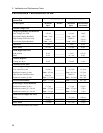
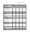
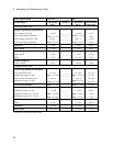
Test Equipment Required
Table 3-1 lists the test equipment required to troubleshoot the power supply. Recommended models are listed.
Table 3-1. Test Equipment Required for Troubleshooting
Type Purpose Recommended Model
GPIB Controller To communicate with the supply via the
GPIB interface
HP Series 300
Digital Voltmeter To check various voltage levels Agilent 3458A
Oscilloscope To check waveforms and signal levels Agilent 54504A/54111A
Electronic Load To test operation of current circuit Agilent 6060B
IC Test Clips To access IC pins AP Products No. LTC
Ammeter/Current
Shunt
To measure output current Guildline 9230/15
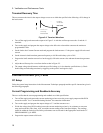
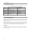
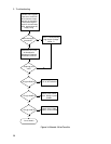
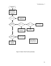
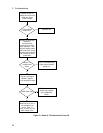
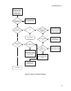
Overall Troubleshooting
Overall troubleshooting procedures for the power supply are given in the Figure 3-1. The procedures first check that
neither an AC input, nor a bias supply failure is causing the problem and that the supply passes the turn-on self test
(error annunciator stays off). The normal turn-on, self-test indications are described in the "Checkout Procedure" in
Chapter 3 of the User's Guide.
If the supply passes the self test and there are no obvious faults, you should perform the verification procedures in
Chapter 2 from the front panel to determine if any functions are not calibrated or are not operating properly. Then
program and read back a voltage via the GPIB to see if the supply responds properly to bus commands. If the supply
fails any of the tests, you will be directed to the applicable flow chart or troubleshooting procedure.
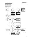
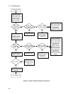
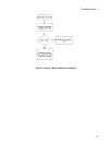
Flow Charts
Troubleshooting flow charts are given in Figure 3-1 sheets 1-10. Several flow charts make reference to the test points
listed in Chapter 6. The circuit locations of the test points are shown on the schematics and on the component
location diagrams in Chapter 6.