


47
4
Principles of Operation
Introduction
This section describes the different functional circuits used in the dc power supply models covered in this manual.
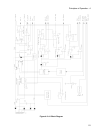
First, the I/O external signals that connect to the Agilent power supply are described. Next, the overall block
diagrams for the dc power supply are described in detail.
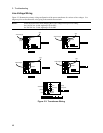
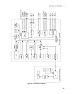
The simplified block diagrams in this section show the major circuits on the dc power supply as well as the signals
between circuits. They also show the reference designations of some of the components in the functional circuit.
These same reference designators are shown in the schematic diagrams in Section 6.
I/O Interface Signals
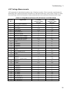
Table 4-1 describes the interface signals between the power supply and the end user (or other external circuits and
devices).
Table 4-1. Power Supply Interface signals
Connector Signal Description
Front panel outputs +OUT
-OUT
Positive DC output voltage
Negative DC voltage (or return)
Rear panel
output/sense screw
terminals
+OUT
-OUT
+ sense
- sense
common
Positive DC output voltage
Negative DC voltage (or return)
+OUT sensing terminal
-OUT sensing terminal
connected to ground conductor
INH/FLT connector
pin 1
pin 2
pin 3
pin 4
FLT/INH mode
1
Digital I/O mode
FLT output OUT 0
FLT Common OUT 1
INH Input IN 2/OUT 2
INH Common Common
1
as-shipped configuration
RS-232 connector XON-XOFF
RTS-CTS
DTR-DSR
NONE
uses ASCII control codes DC# and DC1
uses Request-To-Send and Clear-To-Send lines
uses Data-Terminal-Ready and Data-Set-Ready lines
there is no flow control
GPIB connector GPIB/IEEE 488 Provides the interface to an external GPIB controller
Ac input connector ac mains Can be 100 Vac, 120 Vac, 220 Vac or 240 Vac Input