


4 - Principles of Operation
50
The EEPROM (electrically erasable programmable read-only memory) chip on the A2 interface board stores a
variety of data and configuration information. This information includes calibration constants, GPIB address,
present programming language, and model-dependent data, such as the minimum and maximum values of voltage
and current. One of the EEPROM storage locations holds a checksum value which is used to verify the integrity of
the EEPROM data. Access to the calibration data in the EEPROM is controlled by the combination of a password
and switch settings on A2S201, located on A2 interface board (See Chapter 3 "Inhibit Calibration Switch").
The Dual 12-bit DAC converts the programmed value of voltage and current on the bus into the CV_Prog and
CC_Prog signals, which are sent to the CV control circuits in order to control the magnitude of the output voltage in
the CV mode and output current in CC mode. The CV_Prog and CC_Prog signals are in the 0 to -5 V range, which
corresponds to the zero to full-scale output ratings of the dc power supply.
The Quad 8-bit DAC converts programmed information for the following circuits into analog format: negative offset
trim (OS_Trim_Neg), overvoltage setting (OV_Prog), current measurement range select (Range_Select), and fan
speed programming (Fan_Prog). The OS_Trim_Neg signal allows the negative current control circuit to be
calibrated at zero. The OV_Prog signal is applied to the OV detect circuit, which compares the programmed
overvoltage setting with the actual output voltage. The Range_Select signal selects either the high or the low (20mA)
measurement range. The Fan_Prog signal is applied to the fan speed control circuit in order to speed up the fan as
temperature increases, and to slow the fan speed down as temperature decreases.
The 16-bit ADC in conjunction with a 4x1 multiplexer returns data from the following measurement signals to the
logic array: monitored output voltage (VMon), monitored high-range current (Imon_H), monitored low-range current
(Imon_L), and monitored peak current (Imon_P). All measurement signals are in the range of 0 to +5V, which
corresponds to the zero to full-scale readback capability of the dc power supply.
The 8-channel, 8-bit ADC returns the following signals to the logic array: high-range output current (Imon_H), high
range negative current (Imon_H-), overvoltage (V_Mon), ambient temperature (Temp_Amb), heatsink temperature
(HS_Therm), and output fuse state (Fuse). Five of these signals are for fan control. The logic array varies the
Fan_Prog signal depending upon the ambient temperature, the heatsink temperature, and the present output voltage
and current. The Fuse signal informs the logic array if the output fuse (F300) is open.
A1 Main Board Circuits
Power Circuits
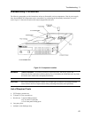
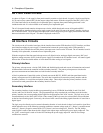
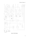
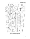
As shown in Figure 4-2, the power circuits consist of: input power rectifiers and filter, current-monitoring resistors,
an output stage, a voltage gain stage, an overvoltage SCR, and an output filter.
The ac input rectifier and filter converts ac input to a dc level. The output stage regulates this dc level at the output
of the power supply. The output stage has up to four parallel NPN transistors mounted on a heatsink and connected
between the +Rail and the +Output. These transistors are driven to conduct by a positive-going signal from driver
Q303 (located in the voltage gain stage). The output stage also has up to four parallel PNP transistors mounted on a
heatsink and connected between the +Rail and the -Rail. These transistors are driven to conduct by a negative-going
signal from driver Q304 (located in the voltage gain stage).
The voltage gain stage is controlled by a signal from the control circuits. A positive-going signal to the voltage gain
stage makes the output more positive. A negative-going signal to the voltage gain stage makes the output more
negative. The Turn-on control signal to the voltage gain stage simply keeps the output of the unit turned off for about
100 milliseconds at power turn-on while the microprocessor is initializing the unit.