


3 - Troubleshooting
38
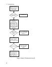
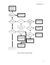
CV/CC Status Annunciators Troubleshooting
The CV/CC annunciators are particularly helpful when troubleshooting a unit with no output. If the unit has no
output voltage or current and one of the annunciators is on then the problem is in the control circuit associated with
that annunciator. An example of how this might be useful would be in a case where the voltage and current are
programmed to some positive value, there is no output voltage and the CV annunciator is on. This indicates that the
problem is probably in the Voltage Amplifier circuit. If the CC annunciator were on then the problem would likely
be in the Current Amplifier. If UNR is indicated then neither the voltage nor the current circuits are in control and
the problem would be in circuits after the gating diodes such as the driver or output regulator stages.
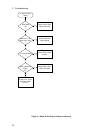
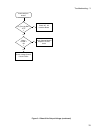
When troubleshooting the CV/CC status annunciators or the status readback circuits, first measure the voltage drop
across the gating diodes; A1 D328 (CV) and D325 (CC). A conducting diode indicates an active (ON) control
circuit. This forward drop is applied to the input of the associated status comparator (U306A and D respectively) and
drives the output (CV_DETECT* or CC_DETECT*) low. The low signal indicates an active status which is sent to
the A2 board microprocessor. The front panel CV annunciator indicates when the CV mode is active
(CV_DETECT* is low). The front panel CC annunciator indicates when the CC mode is active (CC_DETECT* is
low). The UNREGULATED (UNR) annunciator comes on when neither the CV nor CC is active.
Bias and Rail Voltages
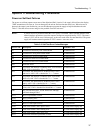
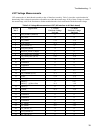
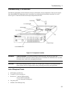
Before troubleshooting any circuit check the bias and/or rail voltages to make sure that they are not the cause. Table
3-3 lists the bias and rail voltage test points for the A1 Main Control , A2 Interface, and the A3 Front Panel/Display
boards. Unless otherwise noted, all voltages are measured with respect to secondary common (R473-3) with no load
on the supply.
Table 3-3. Bias and Reference Voltages
Bias Test Point
(See Figure 6-1)
Common Measurement
+Rail
1
(Agilent
6632B/66332B)
A1 TP 310 - Output +38V 10% (800mV P/P)
+Rail
1
(Agilent 6633B) A1 TP 310 - Output +73V 10% (2.5V P/P)
+Rail
1
(Agilent 6634B) A1 TP 310 - Output +130V 10% (2.2V P/P)
-Rail
1
(Agilent
6632B/66332B)
A1 TP 311 - Output -9.8V 10% (400mV P/P)
-Rail
1
(Agilent 6633B) A1 TP 311 - Output -10.2V 10% (300mV P/P)
-Rail
1
(Agilent 6634B) A1 TP 311 - Output -10.5V 10% (300mV P/P)
+5V secondary A1 R317 Secondary Common +5V 4%
+12V secondary A1 D470 cathode Secondary Common +12V 5%
+15V secondary A1 R318 Secondary Common +15V 4%
-12V secondary A1 D471 anode Secondary Common -12V 5%
-15V secondary A1 R315 Secondary Common -15V 4%
V_Ref A1 R475 Secondary Common +2.5V 6%
+5V Interface
2
E306 (red wire) E 306 (black wire) +5V 3%
1
Measured with respect to - Output at nominal ac input line voltage
2
Measured with reference to Interface Ground (E306 black wire)