


3 - Troubleshooting
44
Cover, Removal and Replacement
a. Using a 2TP Pozi screwdriver, unscrew the two screws that hold the carrying straps to the power supply, and
then remove the two screws from the opposite side of the case.
b. To remove the cover, first spread the bottom rear of the cover slightly and push from the front panel
c. Slide the cover backward until it clears the rear of the power supply.
A2 Interface Board, Removal and Replacement
To remove the Interface Board, proceed as follows:
a. Remove the cover of the power supply as described under, "Cover Removal and Replacement."
b. Remove the two 7 mm and 3/16 inch hex screws that hold the GPIB and RS-232 connectors in place.
c. Unplug the cable from J206. Depress the release button located at the end of the connector where the wires enter
the housing.
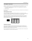
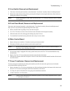
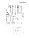
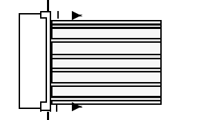
d. Unplug the flat cables. Note the position of the conductive side for reinstallation. Connectors release the cable
by pulling out end tabs as shown by the arrows in the following figure.
e. Lift the board off of the snap-in standoffs.
f. To reinstall the Interface board, perform the above steps in reverse order.
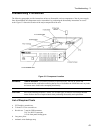
Front Panel Assembly, Removal and Replacement
This procedure removes the front panel assembly from the dc power supply.
a. Remove the Power Supply Cover as described earlier in, "Top Cover Removal and Replacement."
b. Disconnect the cable between the Front Panel board and the Interface board at the Interface board.
c. Carefully peel off the vinyl trim strips on each side of the front panel that cover the front panel screws.
d. Using a Torx T10 driver remove the two screws (one on each side) that hold the front panel assembly to the
chassis.
e. Slide the Front Panel assembly forward and away from the chassis to access the S1 power switch.
f. Disconnect the wires going to the S1 switch assembly. For reassembly, make a note of the color coding of the
wires and the pins to which they are connected.
g . If the supply has front panel binding posts, unplug the cable from the binding post connector and use a Torx T15
driver to remove the screw connecting the ground wire to the chassis.
f. You can now remove the front panel assembly from the supply.
g. To reinstall the Front Panel Assembly, perform the above steps in reverse order.