


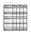
2 - Verification and Performance Tests
18
c. Set up voltmeter to take measurements in the statistical mode as follows:
Press Shift key, f0, Shift key, N
Press ^ (up arrow) until MATH function is selected, then press >.
Press ^ (up arrow until STAT function is selected then press (ENTER).
d. Set up voltmeter to read the average of the measurements as follows:
Press Shift key, f1, Shift key, N.
Press down arrow until RMATH function is selected, then press >.
Press ^ (up arrow) until MEAN function is selected, then press ENTER.
e. Execute the program by pressing f0, ENTER, TRIG, ENTER
f. Wait for 100 readings and then read the average measurement by pressing f1, ENTER.
To repeat the measurement, perform steps (e) and (f).
CC Load Effect
This test measures the change in output current for a change in load from full scale output voltage to short circuit.
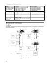
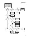
a. Turn off the supply and connect the output as shown in Figure 2-1a with the DVM connected across the current
monitoring resistor.
b. Turn on the supply and program the current to the full scale current value and the output voltage to the
maximum programmable voltage value.
c. Adjust the load in the CV mode for full scale voltage as indicated on the front panel display. Check that the CC
annunciator of the UUT is on. If it is not, adjust the load so that the output voltage drops slightly.
d. Record the output current reading (DVM reading/current monitor resistance value in ohms). You may want to
use the average reading program described under “CC Load and Line Regulation”.
e. Short the load switch and record the output current reading. The difference in the current readings in steps (d)
and (e) is the load effect and should not exceed the limit specified in the performance test record chart for the
appropriate model under CC LOAD EFFECT.
CC Source Effect
This test measures the change in output current that results when the AC line voltage changes from the minimum to
the maximum value within the specifications.
a. Turn off the supply and connect the ac power line through a variable voltage transformer.
b. Connect the output terminals as shown in Figure 2-1a with the DVM connected across the current monitoring
resistor. Set the transformer to the nominal line voltage.
c. Turn on the supply and program the current to the full scale value and the output voltage to the maximum
programmable value.
d. Adjust the load in the CV mode for full scale voltage as indicated on the front panel display. Check that the CC
annunciator of the UUT is on. If it is not, adjust the load so that the output voltage drops slightly.
e. Adjust the transformer to the lowest rated line voltage.
f. Record the output current reading (DVM reading/current monitoring resistor in ohms). You may want to use the
average reading program described under “CC Load and Line Regulation”.
g. Adjust the transformer to the highest rated line voltage.
h. Record the output current reading again. The difference in the current readings in steps (f) and (h) is the CC
source effect and should not exceed the values listed in the performance test record card under CC SOURCE
EFFECT.