


2 - Verification and Performance Tests
14
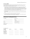
Table 2-2. Programming Ratings
Model Voltage Rating Full Scale Rating Current Rating Full Scale Rating
Agilent
66332A/6632B
Agilent 6633B
Agilent 6634B
20 V
50 V
100 V
20.020 V
50.045 V
100.1 V
5 A
2 A
1 A
5.0045 A
2.002 A
1.001 A
Constant Voltage (CV) Tests
CV Setup
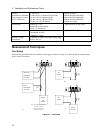
If more than one meter or if a meter and an oscilloscope are used, connect each to the terminals by a separate pair of
leads to avoid mutual coupling effects. For constant voltage dc tests, connect only to +S and -S, since the unit
regulates the output voltage that appears between +S and -S, and not between the (+) and (-) output terminals. Use
coaxial cable or shielded two-wire cable to avoid noise pickup on the test leads.
Voltage Programming and Readback Accuracy
This test verifies that the voltage programming, GPIB readback and front panel display functions are within
specifications. Note that the values read back over the GPIB should be identical to those displayed on the front
panel.
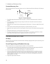
a. Turn off the supply and connect a digital voltmeter between the +S and the -S terminals as shown in
Figure 2-1a.
b. Turn on the supply and program the supply to zero volts and the maximum programmable current with the load
off.
c. Record the output voltage readings on the digital voltmeter (DVM) and the front panel display. The readings
should be within the limits specified in the performance test record chart for the appropriate model under CV
PROGRAMMING @ 0 VOLTS. Also, note that the CV annunciator is on. The output current reading should be
approximately zero.
d. Program the output voltage to full-scale.
e. Record the output voltage readings on the DVM and the front panel display. The readings should be within the
limits specified in the performance test record chart for the appropriate model under CV PROGRAMMING @
FULL SCALE.
CV Load Effect
This test measures the change in output voltage resulting from a change in output current from full load to no load.
a. Turn off the supply and connect the output as shown in Figure 2-1a with the DVM connected between the +S
and -S terminals.
b. Turn on the supply and program the current to the maximum programmable value and the voltage to the full-
scale value.
c. Adjust the load for the full-scale current as indicated on the front panel display. The CV annunciator on the front
panel must be on. If it is not, adjust the load so that the output current drops slightly.
d. Record the output voltage reading on the DVM connected to +S and -S.