


YMF715E
May 21, 1997
-42-
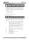
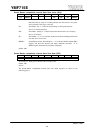
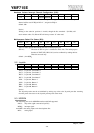
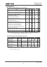
Hardware Volume Interrupt Channel Configuration (R/W):
Index D7 D6 D5 D4 D3 D2 D1 D0
17h - -
IRQ-B MV IRQ-A MV
-***
The Hardware Volume can source interrupt. This register indicates which interrupt
channel will be used. If IRQ-A MV=“1”, assigned to IRQ-A.
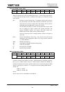
default : 00h
Notice)
Writing to the other bit positions is invalid, though the bits remarked * (D2-D0) will
retain written values. D3, D6 and D7 will always returns “0” when read.
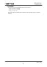
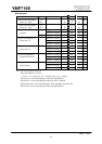
Multi-purpose Select Pin Status (RO):
Index D7 D6 D5 D4 D3 D2 D1 D0
18h ”1” SEL2 SEL1 SEL0 - - - “0”
This is a status register that indicates the state of multi-purpose pin.
SEL2-0... The state of SEL2-0 pins is reflected to these bits. The multi-purpose
function of YMF715E (OPL3-SA3) can be confirmed by reading the bits.
These bits are read only.
default : (1xxx0000)
b
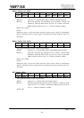
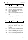
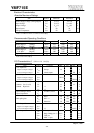
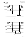
9-2. Joystick
portD7D6D5D4D3D2D1D0
xxh JBB2 JBB1 JAB2 JAB1 JBCY JBCX JACY JACX
JACX... Joystick A, Coordinate X
JACY... Joystick A, Coordinate Y
JBCX... Joystick B, Coordinate X
JBCY... Joystick B, Coordinate Y
JAB1... Joystick A, Button 1
JAB2... Joystick A, Button 2
JBB1... Joystick B, Button 1
JBB2... Joystick B, Button 2
Notice)
The Joystick portion must be re-initialized by writing any value to the Joystick port after resuming
from the power down/save or the Joystick portion power down mode.
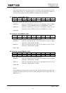
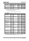
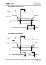
9-3. MODEM
The following pins are for MODEM interface with PnP supported.
/MCS... chip select (eight consecutive byte I/O)
MIRQ... interrupt signal
And MIN is the analog input to mix the telephone line.
MIN... analog input