


YMF715E
May 21, 1997
-20-
3. Download Resource data
When OPL3-SA3 is in the Configuration state, the host can download the resources data to EEPROM
and internal SRAM via 20h: Resource Data Write. To switch OPL3-SA3 into configuration mode,
there are two methods.
First method is to use the normal PnP protocol. After CSN was assigned for all ISA cards by PnP soft-
ware, get CSN from CM (configuration manager) and write the CSN to Wake [CSN], then OPL3-SA3
switches into configuration state.
Second method is to use the YAMAHA Key sequence which is described in the Manual Configuration
mode section. After OPL3-SA3 detects YAMAHA key, OPL3-SA3 switches into the Sleep state.
Writing
“
81h
”
to Wake [CSN] register changes OPL3-SA3 into Configuration state.
After OPL3-SA3 switches into the Configuration state, download the Resource data to EEPROM and
internal SRAM by using following sequence.
1. Write “01h”(RDWE bit = “1”) to 21h: Resource Data Write Enable register to reset
internal address counter and to enable downloading the data.
2. Write Resource data to 20h: Resource Data Write register until downloading data is
completed.
3. Write “00h” to 21h: Resource Data Write Enable register to disable downloading .
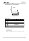
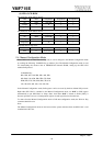
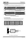
4. External EEPROM
The resource data information of OPL3-SA3 used for PnP auto configuration is stored in external
EEPROM. And either 256 x 16-bit EEPROM or 128 x 16-bit EEPROM, such as 93C55, 93C56,
93C65, 93C66 should be used.
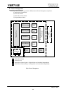
5. Hardware Volume Control
5-1. Hardware Volume up/down/mute Control
Two digital input pins; /VOLUP and /VOLDW can control the master volume of OPL3-SA3.
When /VOLUP is low level, register value of master volume is decremented(-1). When the value
reaches to “00h”(max.0dB), the input signal will not be effective.
When /VOLDW is low level, register value of master volume is incremented(+1). When the value
reaches to “0Fh”(min.-30dB), the input signal will not be effective.
When both of the /VOLUP and /VOLDW are low level simultaneously, volume is muted. When either
/VOLUP or /VOLDW is low level, the previous value becomes effective, and volume is no mute.
5-2. Hardware Volume Interrupt
If configured VEN(Hardware Volume Enable)=1, SA3 Control Register, index 0Ah, D7 bit, when one
of the hardware volume control pins /VOLUP or /VOLDW is asserted or when both are asserted to
request mute, interrupt will be posted in the interrupt channel specified in SA3 Control Register, index
17h, IRQ-A MV or IRQ-B MV bit.
Note that when the muting is in effect, the subsequent mute requests which does not change any
register contents will generate interrrupts. The ignored UP/DOWN requests (UP requests with 0dB
Volume attn., DOWN requests with -30dB) will not generate interrupts.
This bit is cleared upon host’s reading the Master Volume Lch register, SA3 Control Register, index
07h.