


YMF715E
May 21, 1997
-35-
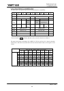
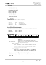
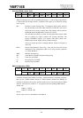
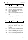
Interrupt (IRQ-B) status (RO):
Index D7 D6 D5 D4 D3 D2 D1 D0
05h - MV OPL3 MPU SB TI CI PI
This register is the status register that indicates which is the interrupt source of IRQB.
When an interrupt occurs, the corresponding bit becomes “1” and its flag (except MV bit)
is cleared when the interrupt routine is completed. This register is not cleared by writing
to this register.
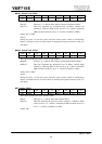
MV... Hardware Volume Interrupt Flag : If configured VEN=1(index 0Ah, D7
bit), the interrupt occurs when either /VOLUP or /VOLDW is low level or
when both are low level to request mute. The interrupt will be posted in
the IRQ-B channel, if IRQ-B MV=1 (index 17h, D5 bit).
Note that when the muting is in effect, the subsequent mute requests which
does not change any register contents will generate interrrupts. The
ignored UP/DOWN requests (UP requests with 0dB Volume attn.,
DOWN requests with -30dB) will not generate interrupts.
This bit is cleared upon host's reading the Master Volume Lch register at
index 07h.
OPL3... Internal FM-synthesizer Timer Flag : Note that this flag will become
undefined for the configurations (SEL=3,4,7) using external synthesizer
(i.e. OPL4-ML/ML2).
MPU... MPU401 Interrupt Flag
SB... Sound Blaster compatible Playback Interrupt Flag
TI... Timer Flag of CODEC
CI... Recording Flag of CODEC
PI... Playback Flag of CODEC
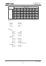
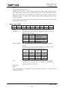
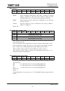
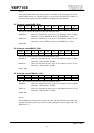
DMA configuration (R/W):
Index D7 D6 D5 D4 D3 D2 D1 D0
DMA-B DMA-A
- SB WSS-R WSS-P - SB WSS-R WSS-P
There are three devices (WSS-P (Windows Sound System CODEC playback), WSS-R
(Windows Sound System CODEC recording) , SB(Sound Blaster compatible playback))
that may use a DMA channel. However 2 DMA channels (DMAA and DMAB) are
available at maximum, this register specifies which device is routed to the physical DMA
channels. And the device written to ”1” is assigned to the corresponding DMA channel.
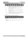
default : 61h
DMA-A: WSS-P
DMA-B: WSS-R + SB
Notice)
Do not assign a device to both DMA-A and DMA-B.