


YMF715E
May 21, 1997
-37-
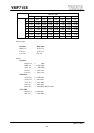
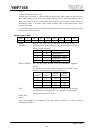
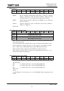
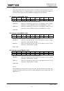
Miscellaneous:
Index D7 D6 D5 D4 D3 D2 D1 D0
0Ah VEN - - MCSW MODE VER2 VER1 VER0
VEN... This bit enables the hardware volume control. Default is VEN=“1”.
MCSW... This bit determines whether Rch of Mic input or loopback of monaural
output is connected to A/D. This will be useful to support the echo
cancellation. When “0” is set to this bit, Rch of Mic input is selected.
MODE... This bit indicates the SB or WSS mode. If MODE=0, it is the SB mode.
This bit is read only.
VER2-0... These bits indicate the version of OPL3-SA3 and read only (VER2=“1”,
VER1=“0”, VER0=“0”).
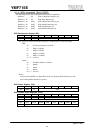
default : 84h
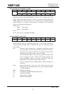
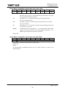
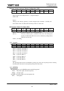
WSS DMA Base counter (R/W):
Index D7 D6 D5 D4 D3 D2 D1 D0
0Bh Playback Base Counter (Low)
0Ch Playback Base Counter (High)
0Dh Recording Base Counter (Low)
0Eh Recording Base Counter (High)
These registers are to load the value to WSS DMA base counter and read out the present
value. Initial value is FFh.
In case of loading the value, both high and low bytes are loaded to internal DMA counter
when the high byte is written. The value set to this register is “(the number of transfer
byte) -1” that is same as WSS CODEC indirect register 0Eh, 0Fh, 1Eh and 1Fh.
When read these registers, the present value of DMA base counter is read out.
These registers are used mainly to support the suspend/resume feature that is very
important for Notebook PC application.
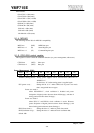
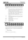
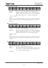
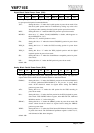
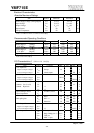
WSS Interrupt Scan out/in (R/W):
Index D7 D6 D5 D4 D3 D2 D1 D0
0Fh - - - - - STI SCI SPI
Use the bits in this register to set WSS interrupt-flags(WSS CODEC indirect Register, index
18h, D6-D4 bits).
STI... “1” in this bit means TI=“1” and corresponding IRQ active.
SCI... “1” in this bit means CI=“1” and corresponding IRQ active.
SPI... “1” in this bit means PI=“1” and corresponding IRQ active.
default : 00h
Notice)
To make IRQ active, it is necessary to set “1” to WSS CODEC indirect register index 0Ah
IEN bit.