


22 En
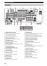
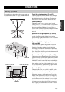
CONNECTIONS
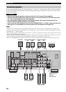
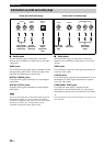
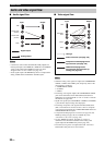
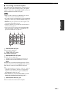
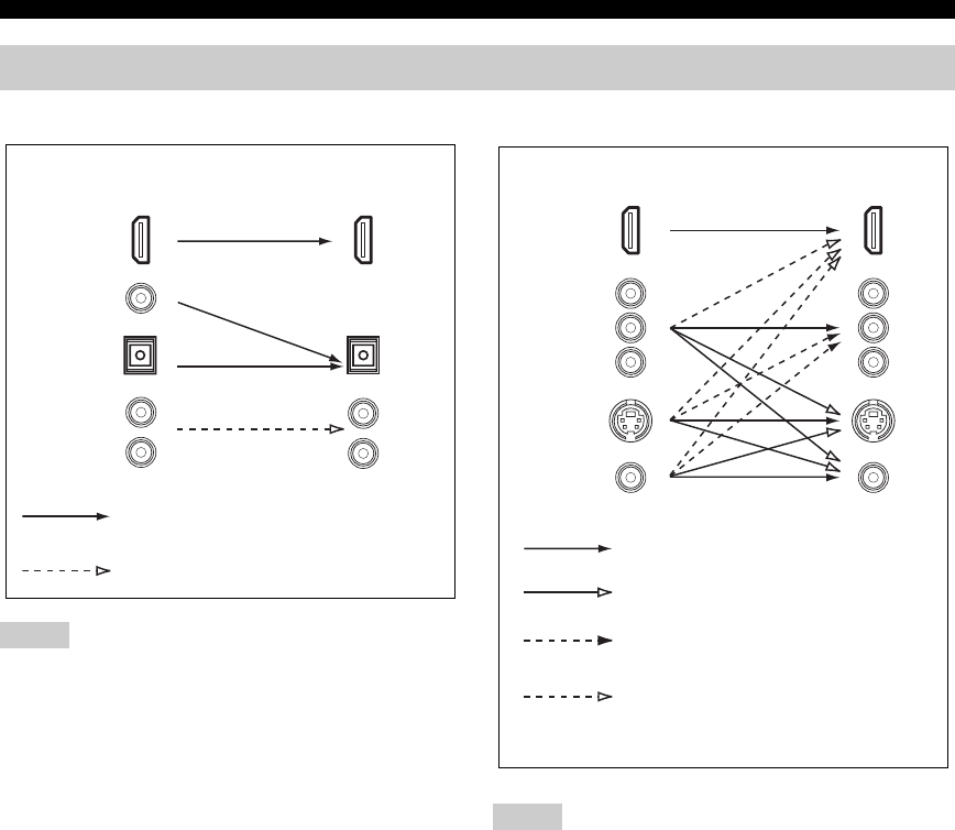
■ Audio signal flow
• 2-channel as well as multi-channel PCM, Dolby Digital and
DTS signals input at the HDMI IN 1, HDMI IN 2 or HDMI IN
3 jack can be output at the HDMI OUT jack only when
“Support Audio” is set to “Other” (see page 115).
• Audio signals input at the HDMI IN jacks are not output at the
analog AUDIO OUT and DIGITAL OUTPUT jacks.
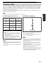
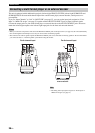
■ Video signal flow
• When the analog video signals are input at the COMPONENT
VIDEO, S VIDEO and VIDEO jacks, the priority order of the
input signals is as follows:
1. COMPONENT VIDEO
2. S VIDEO
3. VIDEO
• The analog video signals output at the COMPONENT VIDEO
jacks can be deinterlaced from 480i (NTSC)/576i (PAL) to
480p/576p. Set “Component I/P” to “On” in “Video” to activate
this feature (see page 102).
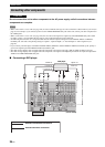
• Digital video signals input at the HDMI IN 1, HDMI IN 2 or HDMI IN
3 jack cannot be output to analog video output jacks.
• The analog component video signals with 480i (NTSC)/576i
(PAL) of resolution are converted to the s-video or composite
video signals and output at the S VIDEO MONITOR OUT and
VIDEO MONITOR OUT jacks.
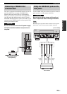
• Component interlace/progressive conversion (see page 102) and
HDMI up-scaling (see page 102) are available only when
“Conversion” is set to “On” (see page 102).
• Use the “HDMI Up-Scaling” parameter in “Video” to
deinterlace and convert the resolution of the analog video
signals output at the HDMI OUT jack (see page 102).
• The GUI screen signal is not output at the VCR 1 OUT and
DVR/VCR 2 OUT jacks and is not recorded.
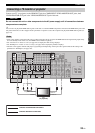
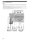
Audio and video signal flow
Notes
DIGITAL AUDIO
(OPTICAL)
DIGITAL AUDIO
(COAXIAL)
HDMI
AUDIO
OutputInput
Analog output
Digital output
Notes
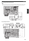
S VIDEO
VIDEO
COMPONENT
VIDEO
HDMI
Through
Output
HDMI interlace/progressive
up-conversion and resolution up-
scaling (see page 102)
Component interlace/progressive
up-conversion (see page 102)
Input
Video conversion (see page 102)