


7
.
www.velodyne.com
Digital Drive User’s Manual
(
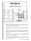
6) LFE INPUT
– T
his XLR input jack receives the balanced LFE signal from your receiver
or processor.
(7) MIC INPUT – This XLR input jack is for your XLR microphone cable.
(8) EQ OUTPUT LEFT/RIGHT
– Connect the audio cable from your accessory kit to these
jacks: white plug to LEFT, and red plug to RIGHT.
(9) THRU
– These RCA connectors are for sharing the same signal that goes into your
subwoofer with a second “daisy
-chained” subwoofer. RCA input comes out of the
THRU jack.
(10) OUTPUT
– These RCA connectors incorporate the use of an 80Hz 6 dB/octave slope
high pass crossover.
(11) INPUT LFE
– This RCA input jack is for line-level connection.
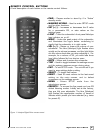
(12) REMOTE SENSOR
– This connection allows for hook-up of the optional remote control
receiver. With the optional receiver plugged in you will be able to utilize all functions
of the remote. Place the infrared receiver within direct line of sight from your usual
listening position.
(13)
VOLUME UP/DOWN
– Pr
ess the black UP pushbutton to incrementally raise your
subwoofer’s system volume; press the black DOWN pushbutton to incrementally
lower your subwoofer’s system volume. Note the use of these buttons during
software update.
(14)
SPEAKER LEVEL INPUT RIGHT/LEFT
– This speaker-level connector allows either
banana plug/jack or exposed wire/terminal connections.