


6
.
www.velodyne.com
Digital Drive User’s Manual
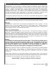
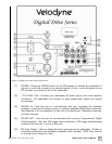
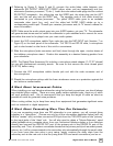
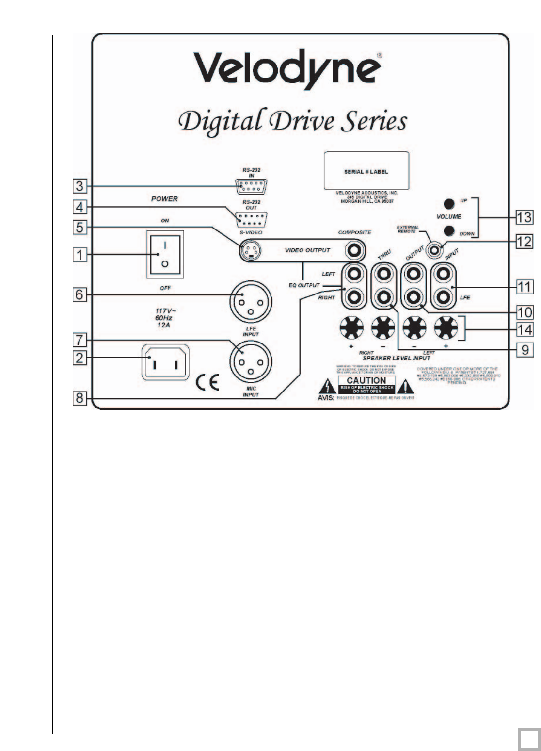
Figure 2: Digital Drive Rear Panel Connections
(1) POWER – Press the POWER switch to the ON position to activate the subwoofer. If
the unit is to be left unused for an extended period of time, move this switch to the
OFF position to prolong the life of the subwoofer.
(2) 117V~60Hz 15A – Connect your detachable AC power plug to this male interface
connection. The detachable cord allows for easy replacement should the original
be damaged.
(3) RS
-232 IN – Use this port to communicate with your computer (for software
updates), a touch panel remote control, or another upstream Digital Drive subwoofer.
See Appendix A for an explanation of the use of the serial port, available commands,
and their formats.
(4) RS
-232 OUT – Use this port to communicate with a second “daisy-chained” Digital
Drive subwoofer
. Also, the 12V trigger featur
e requires a 12V trigger signal (polarity
irrelevant) across pins 7 and 9 of this port.
(5) EQ Video Output
– Used to display the video generated by the subwoofer. S-Video or
composite connections are available (composite cable included). NOTE: Only connect
to a single video output at a time.