TMS320F2809, TMS320F2808, TMS320F2806
TMS320F2802, TMS320F2801, TMS320C2802
TMS320C2801, TMS320F28016, TMS320F28015
SPRS230L–OCTOBER 2003–REVISED DECEMBER 2009
www.ti.com
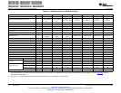
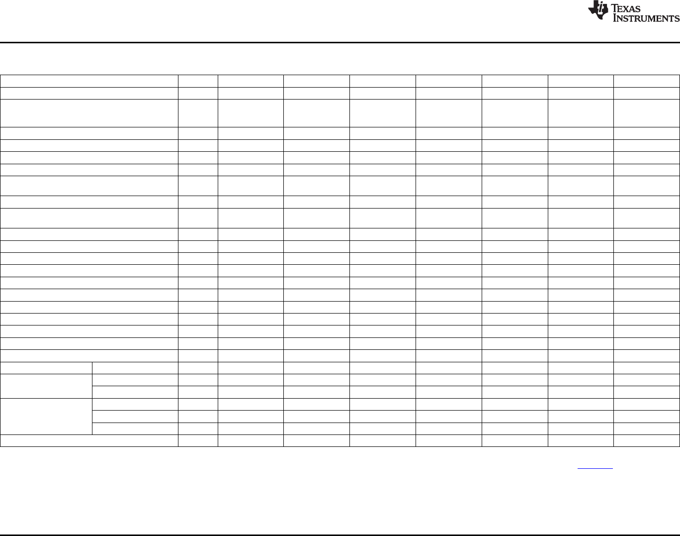
Table 2-1. Hardware Features (100-MHz Devices)
FEATURE TYPE
(1)
F2809 F2808 F2806 F2802 F2801 C2802 C2801
Instruction cycle (at 100 MHz) – 10 ns 10 ns 10 ns 10 ns 10 ns 10 ns 10 ns
18K 18K
10K 6K 6K 6K 6K
Single-access RAM (SARAM) (16-bit word) – (L0, L1, M0, M1, (L0, L1, M0, M1,
(L0, L1, M0, M1) (L0, M0, M1) (L0, M0, M1) (L0, M0, M1) (L0, M0, M1)
H0) H0)
3.3-V on-chip flash (16-bit word) – 128K 64K 32K 32K 16K – –
On-chip ROM (16-bit word) – – – – – – 32K 16K
Code security for on-chip flash/SARAM/OTP blocks – Yes Yes Yes Yes Yes Yes Yes
Boot ROM (4K x 16) – Yes Yes Yes Yes Yes Yes Yes
One-time programmable (OTP) ROM
– 1K 1K 1K 1K 1K – –
(16-bit word)
PWM outputs 0 ePWM1/2/3/4/5/6 ePWM1/2/3/4/5/6 ePWM1/2/3/4/5/6 ePWM1/2/3 ePWM1/2/3 ePWM1/2/3 ePWM1/2/3
ePWM1A/2A/3A/ ePWM1A/2A/ ePWM1A/2A/
HRPWM channels 0 ePWM1A/2A/3A ePWM1A/2A/3A ePWM1A/2A/3A ePWM1A/2A/3A
4A/5A/6A 3A/4A 3A/4A
32-bit CAPTURE inputs or auxiliary PWM outputs 0 eCAP1/2/3/4 eCAP1/2/3/4 eCAP1/2/3/4 eCAP1/2 eCAP1/2 eCAP1/2 eCAP1/2
32-bit QEP channels (four inputs/channel) 0 eQEP1/2 eQEP1/2 eQEP1/2 eQEP1 eQEP1 eQEP1 eQEP1
Watchdog timer – Yes Yes Yes Yes Yes Yes Yes
12-Bit, 16-channel ADC conversion time 1 80 ns 160 ns 160 ns 160 ns 160 ns 160 ns 160 ns
32-Bit CPU timers – 3 3 3 3 3 3 3
Serial Peripheral Interface (SPI) 0 SPI-A/B/C/D SPI-A/B/C/D SPI-A/B/C/D SPI-A/B SPI-A/B SPI-A/B SPI-A/B
Serial Communications Interface (SCI) 0 SCI-A/B SCI-A/B SCI-A/B SCI-A SCI-A SCI-A SCI-A
Enhanced Controller Area Network (eCAN) 0 eCAN-A/B eCAN-A/B eCAN-A eCAN-A eCAN-A eCAN-A eCAN-A
Inter-Integrated Circuit (I2C) 0 I2C-A I2C-A I2C-A I2C-A I2C-A I2C-A I2C-A
Digital I/O pins (shared) – 35 35 35 35 35 35 35
External interrupts – 3 3 3 3 3 3 3
Supply voltage 1.8-V Core, 3.3-V I/O – Yes Yes Yes Yes Yes Yes Yes
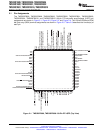
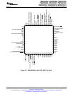
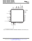
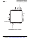
100-Pin PZ – Yes Yes Yes Yes Yes Yes Yes
Packaging
100-Ball GGM, ZGM – Yes Yes Yes Yes Yes Yes Yes
A: –40°C to 85°C – (PZ, GGM, ZGM) (PZ, GGM, ZGM) (PZ, GGM, ZGM) (PZ, GGM, ZGM) (PZ, GGM, ZGM) (PZ, GGM, ZGM) (PZ, GGM, ZGM)
Temperature options S: –40°C to 125°C – (PZ, GGM, ZGM) (PZ, GGM, ZGM) (PZ, GGM, ZGM) (PZ, GGM, ZGM) (PZ, GGM, ZGM) (PZ, GGM, ZGM) (PZ, GGM, ZGM)
Q: –40°C to 125°C – (PZ) (PZ) (PZ) (PZ) (PZ) (PZ) (PZ)
Product status
(2)
– TMS TMS TMS TMS TMS TMS TMS
(1) A type change represents a major functional feature difference in a peripheral module. Within a peripheral type, there may be minor differences between devices that do not affect the
basic functionality of the module. These device-specific differences are listed in the TMS320x28xx, 28xxx DSP Peripheral Reference Guide (literature number SPRU566) and in the
peripheral reference guides.
(2) See Section 5.1 , Device and Development Support Tool Nomenclature, for descriptions of device stages.
12 Introduction Copyright © 2003–2009, Texas Instruments Incorporated
Submit Documentation Feedback
Product Folder Link(s): TMS320F2809 TMS320F2808 TMS320F2806 TMS320F2802 TMS320F2801 TMS320C2802
TMS320C2801 TMS320F28016 TMS320F28015


