9
EN
Hooking Up the Components
Other Hookups
AC OUTLET
b
WIRELESS
REAR
SPEAKER
SPEAKERS
IMPEDANCE USE 8–16 ΩREAR. CENTER
IMPEDANCE USE 8 –16 ΩFRONT A or B A+B
+
R –
AA
BB
– L
+
+
R – – L
+
REAR
FRONT
++
––
CENTER
RL
RL
WOOFER
AUDIO
OUT
VIDEO
OUT
VIDEO
IN
VIDEO
OUT
VIDEO
IN
VIDEO
IN
IN
L
R
L
R
RECOUTIN
CENTER
WOOFER
SIGNAL
GND
COAXIAL
FM
75Ω
AM
AUDIO
IN
L
R
L
R
AUDIO
OUT
AUDIO
IN
y
y
5.1/DVD INPUT
ANTENNA
PHONO
TAPE/MD
MONITOR
VIDEO
TV / LD
FRONT REAR IN
CD
220V
VOLTAGE SELECTOR
240V
120V
AC OUTLET
SWITCHED 120W / 1A MAX
AC 120V 60Hz
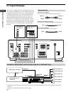
To a wall outlet
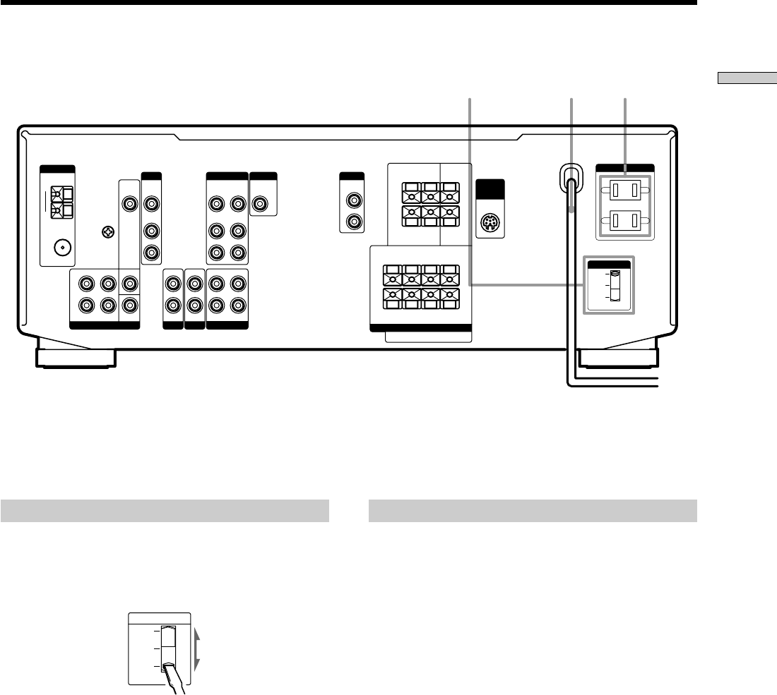
AC power cordVoltage selector
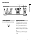
Setting the voltage selector
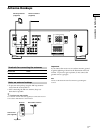
Check that the voltage selector on the rear panel of the
receiver is set to the local power supply voltage. If not,
use a screwdriver to set the selector to the correct position
before connecting the AC power cord to a wall outlet.
VOLTAGE SELECTOR
220V
240V
120V
Connecting the AC power cord
Before connecting the AC power cord of this receiver to a
wall outlet:
• Connect the speaker system to the receiver (see page
11).
• Turn the MASTER VOLUME control to the leftmost
position (0).
Connect the AC power cord(s) of your audio/video
component(s) to a wall outlet.
If you connect other audio/video components to AC
OUTLET on the receiver, the receiver will supply power
to the connected component(s), allowing you to turn on or
off the whole system when you turn on/off the receiver.
Caution
Make sure that the total power consumption of the component(s)
connected to the receiver’s AC OUTLET does not exceed the
wattage stated on the rear panel. Do not connect high-wattage
electrical home appliances such as electric irons, fans, or TVs to
this outlet.


