


18
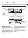
Names and Functions of Parts
Chapter 1 Overview
These connectors input two channels of analog audio.
You can use the A1 INPUT to A4 INPUT items on the
HOME page of the function menu (see page 65) to assign
the signals input to connectors 1/3 (ANALOG1) and
connectors 2/4 (ANALOG2) to audio channels 1 to 4.
You can set the reference input levels with the setup menu
item AUDIO CONTROL >LEVEL SELECT (the factory
default settings are INPUT: +4 dB, REF LEVEL:
–20 dB).
b AUDIO OUTPUT(analog audio signal output) 1/3
and 2/4 connectors (XLR 3-pin, male)
These output two channels of analog audio.
For 4-channel audio, you can use the INTERFACE
SELECT >AUDIO OUTPUT item of the setup menu (see
page 70) to select whether to output channels 1 and 2, or
channels 3 and 4 (factory default setting: channels 1 and
2).
You can set the output level with the setup menu item
AUDIO CONTROL >LEVEL SELECT (factory default
setting: +4 dB) (see page 70).
c AUDIO MONITOR connectors (phono jack)
These output audio signals for monitoring.
You can select the channels to monitor with MONI CH and
MONI SEL on page P1 of the function menu (see page 66).
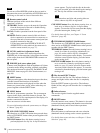
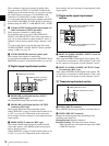
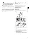
3 Digital signal input/output section
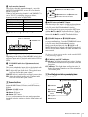
a HDSDI (HD serial digital interface) INPUT
connector (BNC type)
This inputs HD format video and audio signals.
b HDSDI (HD serial digital interface) OUTPUT
connectors (BNC type)
These output HD format video and audio signals.
When CHAR SEL on page P1 of the function menu is set
to “ON” (see page 66), information such as timecode,
menu settings, and error messages is superimposed on the
output signals.
c SDSDI OUTPUT connector (BNC type)
This outputs SDSDI signals downconverted from HD
video input signals, or the SDSDI signals being played
back or being recorded.
When CHAR SEL on page P1 of the function menu is set
to “ON” (see page 66), information such as timecode,
menu settings, and error messages is superimposed on the
output signals.
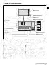
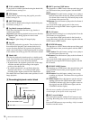
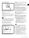
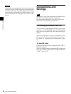
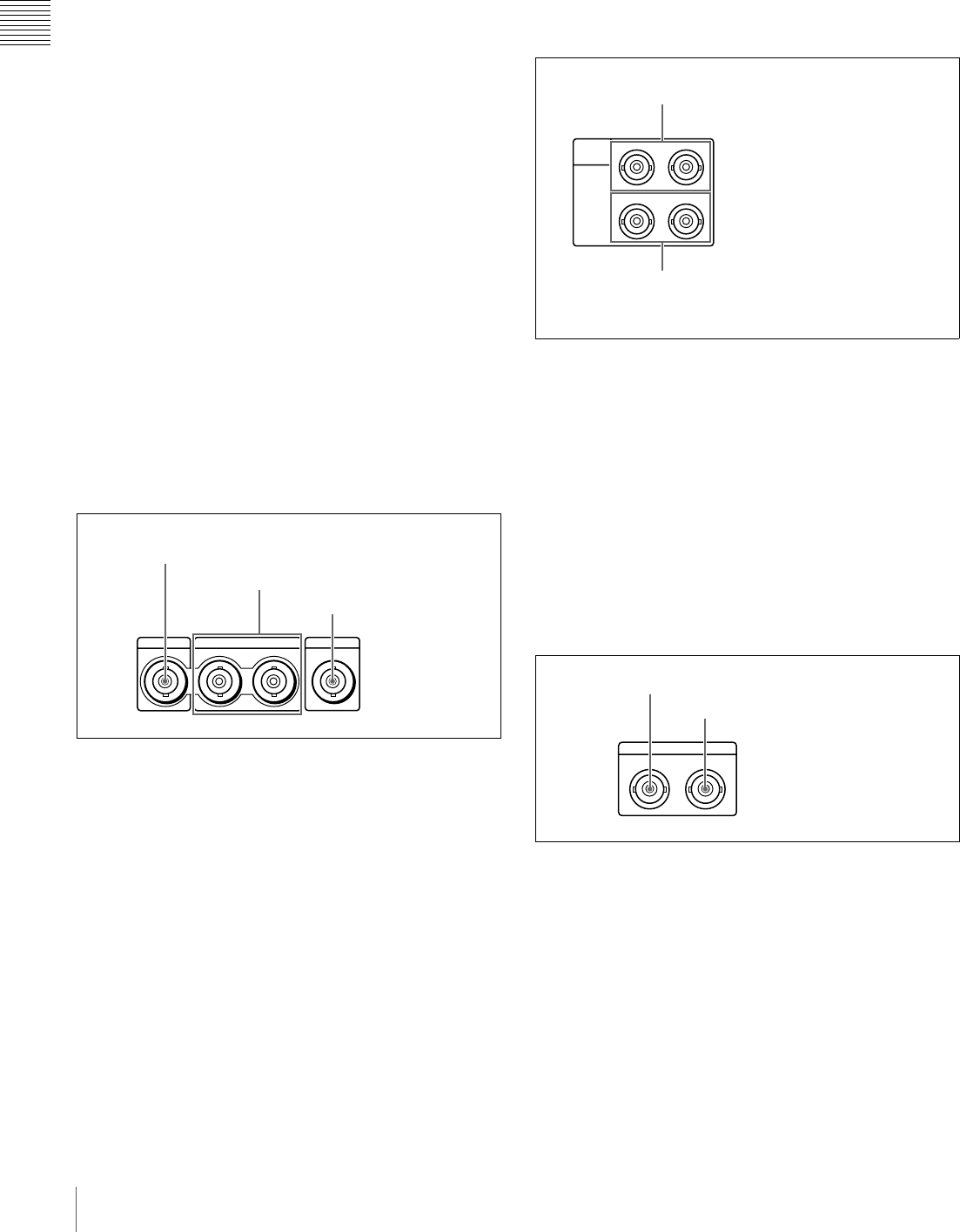
4 Digital audio signal input/output
section
a DIGITAL AUDIO (AES/EBU) INPUT 1/2 and 3/4
connectors (BNC type)
These input AES/EBU format digital audio signals. The
1/2 connector corresponds to audio channels 1 and 2, and
the 3/4 connector corresponds to audio channels 3 and 4.
b DIGITAL AUDIO (AES/EBU) OUTPUT 1/2 and
3/4 connectors (BNC type)
These output AES/EBU format digital audio signals. The
1/2 connector corresponds to audio channels 1 and 2, and
the 3/4 connector corresponds to audio channels 3 and 4.
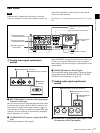
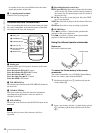
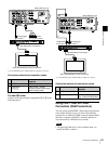
5 Timecode input/output section
a TIME CODE IN connector
Inputs SMPTE timecode generated by an external device.
b TIME CODE OUT connector
Outputs the following timecode, depending on the
operating state of the unit.
During playback: Playback timecode
During recording: The timecode from the internal
timecode generator or the timecode input to the TIME
CODE IN connector.
HDSDI INPUT
HDSDI OUTPUT
12
SDSDI OUTPUT
1 HDSDI INPUT connector
2 HDSDI OUTPUT connectors
3 SDSDI OUTPUT
connector
DIGITAL
AUDIO
(AES/EBU)
1/2
INPUT
OUTPUT
3/4
1/2 3/4
1 DIGITAL AUDIO (AES/EBU) INPUT
1/2 and 3/4 connectors
2 DIGITAL AUDIO (AES/EBU) OUTPUT
1/2 and 3/4 connectors
TIME CODE
IN OUT
1 TIME CODE IN connector
2 TIME CODE OUT connector