


MZ-R900
30
30
30
30
30
30
R831
C808
C807
R806
C804
R807
C835
R619
R607
C834
C613
C619
R610
R606
C629
C630
R809
R808
C802
C812
C818
R817
C814
R814
R845
R840
R838
R812
R810
R802
R803
R801
C621
R613
R837
R839
C806
R828
C819
R829
C820
C833
R804
C805
R833
R835
C803
R805
C823
R830
C522
C560
C552
C551
C512
C554
+
C553
+
C556
+
C555
+
C558
C559
C557
R604
R605
R917
R921
R908
R907
C307
C308
C334
+
L905
C332
+
C322
+
C113
+
C213
+
C310
+
C907
C311
+
C903
+
C104
+
C204
+
C309
+
C313
+
R308
C312
+
C831
+
C826
L554
L553
L903
L551
L904
D603
KA
Q602
L601
L901
L902
RB801
RB551
RB552
RB553
CN501
C625
+
IC805
C832
L552
S802
SYNCHRO REC
ON T OFF
S801
HOLD
HOLD T OFF
S803
PROTECT
DETECT
S805
OPEN
S804
BATTERY IN
DETECT
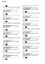
OPTICAL
PICK-UP BLOCK
(LCX-4R)
i / LINE OUT
J302
J301(1/2)
LINE IN
(OPT)
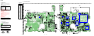
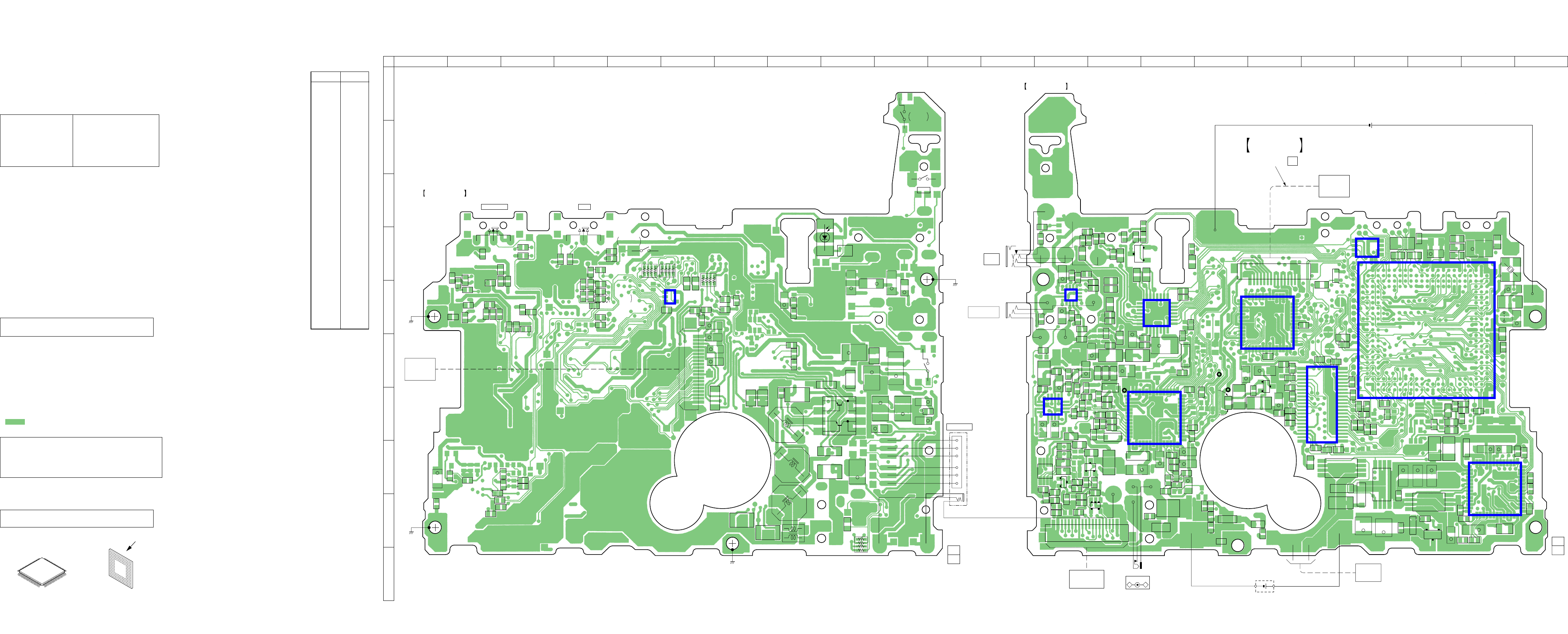
MAIN BOARD
(COMPONENT SIDE)
1-679-610-
11
(11)
1
20
3
1
4
5
S806
(OPEN/CLOSE DETECT)
05
Q302
G
D
S
R318
R317
C211
R212
R211
C111
R111
C210
C314
C323
+
C116
C118
C117
R118
C318
C320
+
R218
C216
C217
C218
R201
R102
R101
C101
C112
C212
R112
C110
C340
C330
R302 R307
C203
C103
C201
C305
+
R319
C344
R310
L303
C316
+
C105
+
C205
+
C329
C106
R104
R105
C836
R103
R846
C206
R203
R205
C335
C338
FB306
FB305
FB304
FB303
FB302
FB301
R816
R815
R303
R301
R309
C303
+
C315
+
C304
L302
C925
C924
C923
C922
D303
AK
C906
R905
R910
C908
R813
R903
R915
C337
R811
C825
R204
Q801
C1
C2
B2
E
B1
F801
D904
KA
R902
C905
C921
R909
R941
D903
KA
C306
C302
L301
C904
+
D901
AK
C901
+
D602
AK
C601
R936
R947
C902
+
R948
R906
R901
R912
R949
C301
+
C914
R306
C336
R305
R304
C913
R920
D902
AK
C926
C915
C917
R911
C919
+
C920
+
R946
C911
+
C602
R602
C605
R603
C524
+
R519
R521
L502
L501
D605
AK
C837
R622
C633
C529
+
C521
C501
R501
R507
C503
C504
C518
+
C526
C505
C506
C507
C523
C530
C502
C561
R841
R517
R505
C508
C827
R844
C509
C510
C516
C515
C514
C532
C519
C511
C513
R832
R312
C604
R601
R825
C822
FB803
FB801
FB802
FB804
C811
C821
+
C817
C828
C829
R824
C815
+
C810
R822
C816
R823
R821
C612
+
C611
+
R611
C614
C610
+
C618
C616
X801
C830
+
L801
C809
+
C813
C801
R608
C606
R608
C607
R621
R620
Q601
G
D
S
C631
+
D601
AK
C608
D607
AK
L603
L602
C603
+
C626
+
Q605
5
8
4
1
41
41
Q604
Q603
5
8
4
1
C623
+
C624
+
C609
+
IC601
*
IC801
IC501
144
22 23
IC551
IC301
IC901
IC302
D301
K
A/K
A
D302
IC303
18151015
CN801
D606
KA
D608
KA
C615
15 10 5 1
CN502
D801
KA
IC804
L802
B
C
E
Q803
B
C
E
Q501
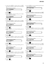
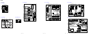
SWITCH
&
LCD MODULE UNIT
MOTOR FLEXIBLE
BOARD
1-679-392-
11
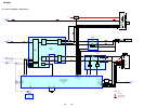
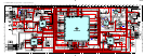
MAIN BOARD
(CONDUCTOR SIDE)
1-679-610-
11
(11)
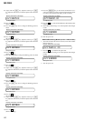
J303
MIC
(PLUG IN POWER)
J301(2/2)
LINE IN
(OPT)
RECHARGEBLE
BATTERY
(NICKEL-METAL)
NH-14WM
1.2V 1400mAh
DRY BATTERY
SIZE “AA”
(IEC DESIGNATION R6)
1PC. 1.5V
TH601
DC IN 3V
–
+
J601
56
43
15
28
114
4229
114
42 29
15
28
56
43
56
43
15
28
114
4229
28 22
814
1
7
21
15
16
13
5
8
129
14
5
8
4
1
14
129
5
8
16
13
24223923723633230
32234240
131437
1112241
51048
316
7229
9419
189596
22827
341521
381723
401628
262025
4224113
513031
453635
475044
534959
565455
615762
5860
68
63
81
137
65
70
135
67
77
133
74
79
131
66737684
80
83
130
91
87
92
129
143
94
88
128
103
97
104
127
98
101
105
243
119
99
112
114
102
120
117
100
121
69 71
116
111
122
64
115
110
123
78
93
109
124
75
72
108
86
85
107
82
90
145
106
89
159
164
118
147
157
125174170
126224172
132161180
134149182
136166181
138
154
153
151
142
139168165
141146140
163148152
183179185
193189191
205206207
156158232
169160144
171167150
231175178
195197187
23852
39412354346233229227190213200202225208210211209201203204155
218222219214198192186223217188220226162177
212194221196215184216176228173199
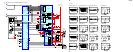
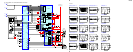
123 4 5 6 7 8 9 10 11 12 13 14 15 16 17 18 19 20 21 22
A
B
C
D
E
F
G
H
I
J
T601
SL801(TEST)
(CHASSIS)
(CHASSIS)
(CHASSIS)
(CHASSIS)
MD
MECHANISM
AP915
(VL)
AP914
(VC)
AP912
(GND)
1
4
8
5
(BATTERY CASE)
HR601
OVER WRITE
HEAD
85
14
TP
(–)
TP
(+)
EXECEPT
US, Canadian
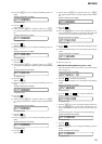
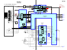
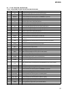
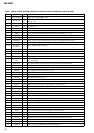
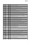
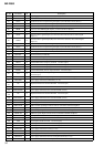
6-4. PRINTED WIRING BOARDS
D301 H-13
D302 H-13
D303 F-13
D601 I-20
D602 I-15
D603 F-9
D605 I-16
D606 I-19
D607 H-21
D608 H-18
D801 D-18
D901 H-14
D902 F-15
D903 G-14
D904 G-14
IC301 E-15
IC302 G-13
IC303 E-13
IC501 G-18
IC551 E-17
IC601 H-21
IC801 E-20
IC804 D-19
IC805 E-6
IC901 G-15
Q302 D-14
Q501 F-17
Q601 I-20
Q602 G-9
Q603 I-20
Q604 H-19
Q605 H-18
Q801 I-14
Q803 H-14
• Semiconductor
Location
Ref. No. Location
Note on Schematic Diagram:
• All capacitors are in µF unless otherwise noted. pF: µµF
50 WV or less are not indicated except for electrolytics
and tantalums.
• All resistors are in Ω and
1
/
4
W or less unless otherwise
specified.
• % : indicates tolerance.
• C : panel designation.
• A : B+ Line.
• Total current is measured with MD installed.
• Power voltage is dc 3 V and fed with regulated dc power
supply from external power voltage jack.
• Voltages and waveforms are dc with respect to ground in
playback mode.
no mark : PLAYBACK
( ) : REC
∗
: Impossible to measure
• Voltages are taken with a VOM (Input impedance 10 MΩ).
Voltage variations may be noted due to normal produc-
tion tolerances.
• Waveforms are taken with a oscilloscope.
Voltage variations may be noted due to normal produc-
tion tolerances.
• Circled numbers refer to waveforms.
• Signal path.
E : PLAYBACK
k : REC (ANALOG IN)
l : REC (DIGITAL IN)
• The voltage and waveform of CSP (chip size package)
cannot be measured, because its lead layout is different
form that of conventional IC.
* Replacement of IC801 used in this set requires a
special tool.
Note on Printed Wiring Board:
• X : parts extracted from the component side.
• Y : parts extracted from the conductor side.
• : Pattern from the side which enables seeing.
(The other layers' patterns are not indicated.)
Caution:
Pattern face side: Parts on the pattern face side seen from
(Conductor Side) the pattern face are indicated.
Parts face side: Parts on the parts face side seen from
(Component Side) the parts face are indicated.
• MAIN board is four-layer printed board.
However, the patterns of layers 2 and 3 have not been
included in this diagrams.
* Replacement of IC801 used in this set requires a
special tool.
• Lead Layouts
surfac
e
Lead layout of conventional IC CSP (chip size package)
Note:
The components identi-
fied by mark 0 or dotted
line with mark 0 are criti-
cal for safety.
Replace only with part
number specified.
Note:
Les composants identifiés par
une marque 0 sont critiques
pour la sécurité.
Ne les remplacer que par une
pièce portant le numéro
spécifié.