


3
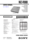
MZ-R900
NOTES ON HANDLING THE OPTICAL PICK-UP
BLOCK OR BASE UNIT
The laser diode in the optical pick-up block may suffer electro-
static break-down because of the potential difference generated
by the charged electrostatic load, etc. on clothing and the human
body.
During repair, pay attention to electrostatic break-down and also
use the procedure in the printed matter which is included in the
repair parts.
The flexible board is easily damaged and should be handled with
care.
NOTES ON LASER DIODE EMISSION CHECK
Never look into the laser diode emission from right above when
checking it for adjustment. It is feared that you will lose your sight.
NOTES ON HANDLING THE OPTICAL PICK-UP BLOCK
(LCX-4R)
The laser diode in the optical pick-up block may suffer electro-
static break-down easily. When handling it, perform soldering
bridge to the laser-tap on the flexible board. Also perform mea-
sures against electrostatic break-down sufficiently before the op-
eration. The flexible board is easily damaged and should be handled
with care.
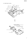
OPTICAL PICK-UP FLEXIBLE BOARD
SECTION 1
SERVICING NOTES
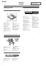
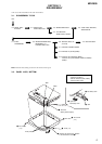
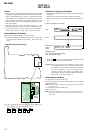
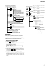
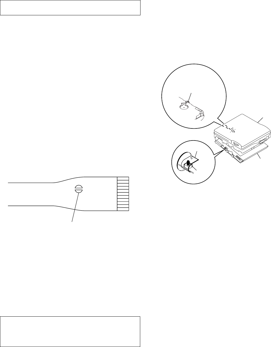
• In performing the repair with the power supplied to the set,
removing the MAIN board causes the set to be disabled.
In such a case, fix a convex part of the open/close detect switch
(S806 on MAIN board) with a tape in advance.
Handle the FLEXIBLE board (overwrite head) with care, as it
has been soldered directly to the MAIN board.
In repairing the component side of MAIN board, connect the
FLEXIBLE board (overwrite head) and the MAIN board with
the lead wires in advance. (See page 7)
laser-tap
upper panel assy
MAIN board
Tape
S806
FLEXIBLE board
(Over write head)
• Replacement of CDX2671-203GA (IC801) used in this set
requires a special tool.
• On the set having the microcomputer version 1.000, some
adjusted values were set in the manual mode at the shipment,
but these data will be cleared when the NV is reset. Therefore,
on the set having the microcomputer version 1.000, change the
adjusted values following the Change of Adjusted Values
immediately after the NV was reset. (See page 17)
• If the nonvolatile memory was replaced on the set, the modified
program data must be written to the nonvolatile memory. In such
a case, write the modified data that meets the microcomputer
version following the patch data rewriting procedure at the
replacement of nonvolatile memory. (See page 22)
Notes on chip component replacement
• Never reuse a disconnected chip component.
• Notice that the minus side of a tantalum capacitor may be dam-
aged by heat.
Flexible Circuit Board Repairing
• Keep the temperature of the soldering iron around 270 ˚C dur-
ing repairing.
• Do not touch the soldering iron on the same conductor of the
circuit board (within 3 times).
• Be careful not to apply force on the conductor when soldering
or unsoldering.
CAUTION
Use of controls or adjustments or performance of procedures
other than those specified herein may result in hazardous ra-
diation exposure.