


19
MZ-R900
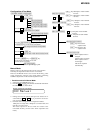
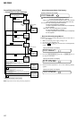
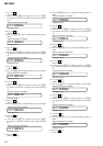
7. Press the N key, and set the laser CD read adjustment
mode (item number 012).
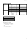
8. Check that the laser power meter reading is 0.97 ± 0.10 mW.
9. Check that the voltage both ends (TP (+) and TP (–)) of resistor
R521 at this time is below 44 mV.
10. Press the N key, and set the laser MO write adjustment mode
(item number 013).
11. Check that the laser power meter reading is 4.95 ± 0.50 mW.
12. Check that the voltage both ends (TP (+) and TP (–)) of resistor
R521 at this time is below 80 mV.
13. Press the x key to quit the manual mode, and activate the
test mode (display check mode).
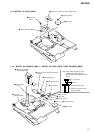
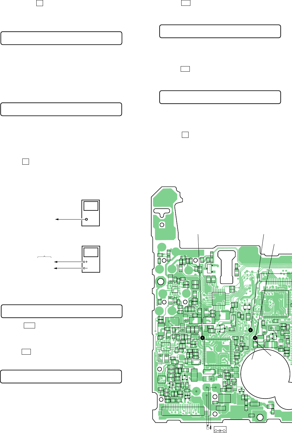
Checking and Connection Location: MAIN board
Adjustment/checking and Connection Location:
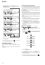
2. When press the X key to write the adjusted value, LCD dis-
plays as follows and power supply manual adjustment has com-
pleted.
Adjustment and Connection Location:MAIN board
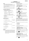
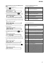
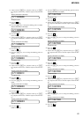
Temperature Correction
• Adjustment Method of temperature correction
1. Select the manual mode of test mode, and set the mode num-
ber 014 (see page 13).
2. Measure the ambient temperature.
3. Adjust with [VOL +], [VOL --] key so that the adjusted value
(hexadecimal value) becomes the ambient temperature.
(Initial value: 14h = 20 °C, Adjusting range: 80h to 7fh (–128
°C to +127 °C)
4. Press the X key to write the adjusted value.
000 ADJ OK
Remote commander LCD display
014 SetTmp **
Remote commander LCD display
**
: Adjusted value
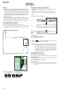
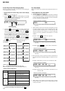
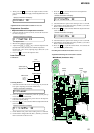
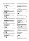
Laser Power Check
Connection :
Checking Method :
1. Select the manual mode of test mode (see page 13), and set the
laser power adjusting mode (item number 010).
2. Press the . key continuously until the optical pick-up
moves to the most inward track.
3. Open the cover and set the laser power meter on the objective
lens of the optical pick-up.
4. Press the N key, and set the laser MO read adjustment mode
(item number 011).
5. Check that the laser power meter reading is 0.81 ± 0.08 mW.
6. Check that the voltage both ends (TP (+) and TP (–)) of resistor
R521 at this time is below 44 mV.
digital voltmeter
MAIN board
laser
power meter
Optical pick-up
objective lens
TP (+)
TP (–)
010 Laser
Remote commander LCD display
011 LrefPw **
Remote commander LCD display
012 HrefPw **
Remote commander LCD display
013 WritPw **
Remote commander LCD display
Q302
G
D
S
C325
C326
R318
R317
C211
R212
R211
C111
R111
C210
C314
C323
+
C116
C118
C117
R118
C318
C320
+
R218
C216
C217
C218
C202
R202
R201
C102
R102
R101
C101
C112
C212
R112
C110
C340
C330
R302 R307
C203
C103
C201
C305
+
R319
C327
C344
R310
L303
C316
+
C105
+
C205
+
C331
C329
C106
R104
R105
C836
R103
C107
R846
C206
C207
R203
R205
C335
C338
C317
C324
C333
C319
C328
FB306
FB305
FB304
FB303
FB302
FB301
R816
R815
R303
R301
R309
C345
+
C303
+
C315
+
C304
L302
C925
C924
C923
C922
R942
D303
AK
C906
R905
R904
R910
C908
R813
R903
R915
C337
R811
C825
R204
Q801
C1
C2
B1
E
B2
F801
D904
KA
R902
C905
C921
R909
R941
D903
KA
C306
C302
L301
R916
C904
+
C927
D901
AK
C901
+
D602
AK
C601
R936
R947
C902
+
R913
R948
R906
R901
R912
R949
C301
+
C914
C912
R306
C336
R305
R304
C913
C910
C909
R920
D902
AK
C926
R919
C915
C918
R932
R916
R918
R917
R911
C919
+
C920
+
R946
C911
+
C602
R602
C605
R603
R914
C928
C525
C524
+
R519
R521
L502
L501
D605
AK
C837
R622
C633
C529
+
C521
C501
C531
R501
R502
R507
C503
C504
C518
+
C526
C505
C506
C507
C
IC551
IC301
IC901
IC302
D301
K
A/K
A
D302
IC303
IC902
181 5 10 15
CN801
Q903
BCE
15 10 5 1
CN502
B
C
E
Q803
S
D
G
Q904
B
C
E
Q501
TH601
DC IN 3V
–
+
J601
114
42 29
15
28
56
43
56
43
15
28
114
4229
28 22
814
1
7
21
15
16
13
5
8
129
14
21
34
14
129
5
8
16
13
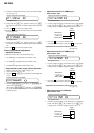
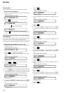
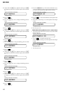
– MAIN Board (Conductor side) –
AP912
(GND)
AP914
(VC)
AP915
(VL)
TP (+)
TP (–)