


1-69
DFS-700/700P
Chapter 6 System Connections and
Settings
6-8
Chapter 6 System Connections and Settings
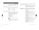
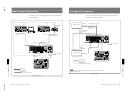
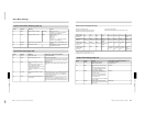
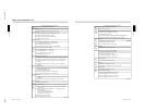
System Information Display (page 2/8)
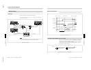
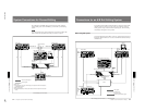
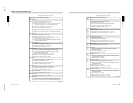
Input Video Setup (page 3/8)
Button Setting Meaning
Values
F1 INFO Display options installed. CONFIG r BKDF-701/711/712
(Appears as “***” when not installed.)
To return, press F5(EXIT r).
F2
INFO Display software version.
VER r DFS-700/700P :x.xx
BKDF-712: x.xx
DATA: x.xx
Panel: x.xx
(Appears as “----” when not installed.)
To return, press F5(EXIT r).
F3
PW ON Select setup mode at power on. FACTRY (factory default)/USER (user
settings)
F5
INSTL
Install new software.
r Press F3(OK) to confirm install; press
F5(CANCEL) to cancel.
Button Setting Meaning
Values (First value is factory default.)
F1 In No. Select input to set. 1/2/3/4/5/6/7/8/DSK
F2
TYPE Select input signal format.
SDI/YUV/Cps/YC/RGB/***
(Only types which can be set appear.
See the table
on the next page.
When F1(In No.) is set to DSK,
appears as “***”.)
F3
TBC TBC Center setting for the input
signal
The output signal is output in the
correct phase if the phase
relationship of the center value with
respect to the reference
synchronizing signal is in the range
±0.3H.
0H/0.5H/1H/***
This setting is not possible when TYPE is Cps or
YC.
F4
+H–pos
Video phase adjustment of input
signal
• When SDI, YUV, Cps, YC, or RGB is selected, this
can be adjusted from –24 to +24 in steps of 2.
• When DSK is selected, this can be adjusted from
–30 to +31 in steps of 1.
F5
+XPT
Cross-point button assignment to
input signals
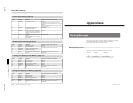
Setup Menu Settings
1/2/3/4/5/6/7/8/***
(When F1(In No.) is set to DSK, appears as “***”.)
To assign a signal, hold down the function key, and
press a cross-point button on the background bus.
Chapter 6 System Connections and
Settings
Chapter 6 System Connections and Settings
6-9
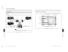
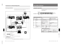
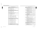
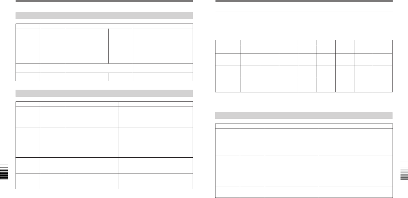
a) Setup menu item CpnIN set to “IN 1-4”
b) Setup menu item CpnIN set to “IN 5-8”
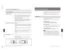
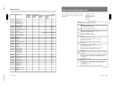
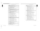
Output Video Setup (page 4/8)
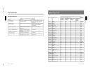
Primary inputs and signal formats
SDI: serial digital signals
Component: analog component signals
Composite: analog composite signals
Input number
1234
5
678
With standard
equipment
SDI SDI SDI SDI Component Component Component Component
RGB
With BKDF-701
installed
SDI
Component
SDI
Component
SDI
Component
SDI
Component
RGB
SDI
Component
SDI
Component
SDI
Component
SDI
Component
With BKDF-702/
702P installed
(mode 1)
a)
SDI
Component
SDI
Component
SDI
Component
SDI
Component
RGB
Composite
YC
Composite
YC
Composite
YC
Composite
YC
With BKDF-702/
702P installed
(mode 2)
b)
SDI SDI SDI SDI Component
Composite
YC
Component
Composite
YC
Component
Composite
YC
Component
RGB
Composite
YC
YC: analog YC signals
RGB: analog RGB signals (G signal with sync)
Button Setting Meaning
Values (First value is factory default.)
F1 CLEAN Select output video from
CLEAN OUT connector.
CLEAN/KEYOUT/PVW
(See page 2-15.)
F2
CLIP Toggle white clip and dark clip on/
off.
Only valid for SDI output signals,
and the SDI standard white and
dark values are applied.
OFF/ON
F3
T-Area Toggle safe title indication on
preview video using CLEAN OUT
connector on/off.
When on, the safe title indication
shows approximately 85% of the
whole image area.
This item appears when F1(CLEAN)
is set to “PVW”.
OFF/ON
F4
FLD FZ
Select the field output when the
internal frame memory is set to field
freeze mode.
ODD/EVEN