Chapter 5 Control From Editing
Control Units
5-8
Chapter 5 Control From Editing Control Units
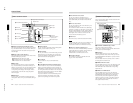
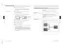
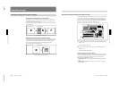
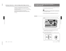
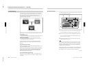
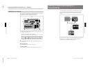
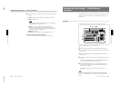
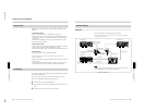
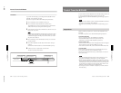
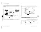
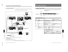
Control From the BVE-900/2000 Series
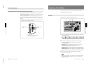
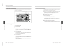
You can combine the DFS-700/700P with a BVE-900/910 or BVE-2000
Series Editing Control Unit to carry out A/B roll editing using two players
and one recorder.
For details of preread editing, see the section “Preread Editing” (page 5-14).
Connectable editing control units
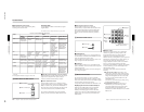
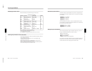
To control the DFS-700/700P, the BVE-900/910/2000 and optional BKE-
913 board (for BVE-900/910) must have the following ROM versions or
higher.
BVE-900 Ver. 1.11 or later
BVE-900 with BKE-900K Ver. 2.01 or later
BVE-910 Ver. 1.02 or later
BKE-913 Ver. 1.06 or later
BVE-2000 Ver. 1.10 or later
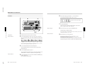
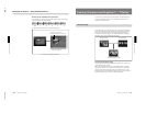
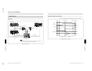
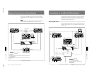
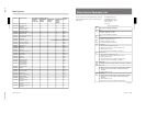
Control using editor control signals
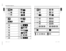
You can control the following DFS-700/700P functions using 9-pin serial
control signals from the BVE-900/910/2000. Input these signals to the
EDITOR connector on the rear panel of the DFS-700/700P. The functions
marked with an asterisk below can only be controlled from the BKE-900
after installation of the optional BKE-900K board.)
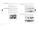
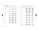
•Background image (FROM source) and foreground image (TO source)
selection
•Pattern number selection
•Transition direction (normal or reverse) selection
•Transition duration selection
•Automatic transition execution
•Downstream key on and off
•Snapshot saving and recall*
•Saving and loading DFS-700/700P data (snapshots and user program
effects)*
Notes
•It is not possible to load and save user program effects or snapshots from
the BVE-900/910.
•KEY FADE IN and KEY FADE OUT cannot be used. Also, KEY WIPE
OUT and KEY MIX OUT can only be used with versions 2.24 and later
of the BVE-2000.
When using KEY WIPE OUT, the effect must be executed in the reverse
direction.
Chapter 5 Control From Editing
Control Units
Chapter 5 Control From Editing Control Units
5-9
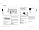
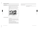
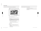
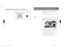
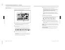
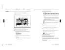
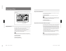
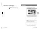
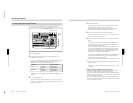
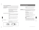
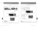
Downstream key control using GPI signals
You can use signals from the GPI output connector on the BVE-900/910/
2000 to turn the DFS-700/700P downstream key function on and off. Input
the GPI signals to the T2 connector on the rear panel of the DFS-700/
700P. (The BVE-2000 can also use 9-pin serial control signals to turn the
downstream key on and off and to set the transition duration.)
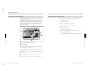
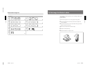
Preparations
Make the following preparations to control the DFS-700/700P from the
BVE-900/2000-series editor.
For details about operation, refer to the Operating Instructions or User’s Guide
supplied with the editor.
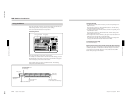
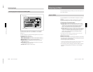
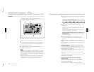
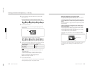
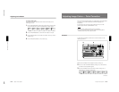
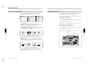
On the DFS-700/700P
•In page 1 of the setup menu, set F3(PORTS) to “PVE-500”.
•To accept 9-pin serial control signals, press the EDITOR button on the
control panel, turning it on. To accept GPI signals, press the GPI button,
turning it on.
(When the DFS-700/700P is powered on, it accepts either 9-pin serial
control signals or GPI signals.)
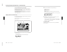
•To improve editing accuracy, supply a reference sync signal to the VCRs
and editing control unit from the BLACK BURST OUT connectors on
the DFS-700/700P.
On the recorder VCR
Set the recorder VCR so that it enters PB (playback) mode when stopped.
(If the VCR has a selector for PB or PB/EE, set it to PB.)
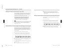
On the BKE-900/910
Set the PVW (preview) mode to EE.
•BVE-900 with no BKE-900K installed: In SYSTEM SETUP mode, set
BYTE-1 of the MAIN BLOCK INTERFACE parameters to hexadecimal
“01” (EE).
•BVE-910, or BVE-900 with BKE-900K installed: In SYSTEM SETUP
mode, set PVW MODE under SW’ER CONFIGURATION to EE.
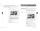
On the BVE-2000
•In SYSTEM SETUP mode, set PVW MODE under SW’ER
CONFIGURATION to EE.
•In SYSTEM SETUP mode, set SW’ER TYPE under SW’ER
CONFIGURATION to DFS.
However, for versions 2.24 and later of the BVE-2000, select DFS-700/
700P.