42
Connecting to the Control System
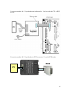
The in-circuit programmer connects to the control system board with 4 signals including
a clock, data, MCLR and ground. The connection at the programmer end is a 10 pin (2x5)
header connector. The connection at the control system board end is either a 10 pin (2x5)
pin header or a DB15 connector depending on which version of which board you are
programming. This table shows which board support which kind of connector.
10 Pin
Header DB-15
CPU v1.0
RCB pre-production
RCB v1.0
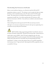
The simple 10 pin header to 10 pin header ribbon cable can be used with all boards. The
advantage o
f the DB15 connector on the RCB boards is that you can leave the boards
plugged in the card cage while downloading new firmware.
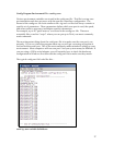
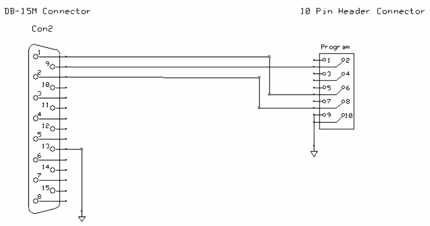
Optional cable for programming the local CPU on the RCB
Pins used for building an in-circ
uit programming interface:
Pin Use
1 PGD
2 PGC
13 Ground
15 MCLR


