12
Configuring the Backplane
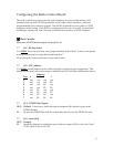
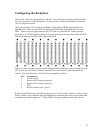
The system will come configured as ordered. You will need to plug the various boards
into the correct slots in the backplane. If your system is already assembled as desired,
you can skip this section.
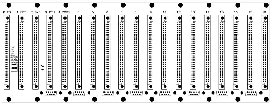
The Power Supply, CPU and the first Radio Control Board (RCB) must be placed in
specific slots. After the first RCB, all additional RCBs must be installed next to each
other. There can be no gaps between the CPU and any of the RCBs. When optional
microwave or CTCSS signaling boards are used, these boards are paired with each RCB
and are installed in the slot to the right of the RCB.
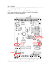
The basic control system consists of the card rack with backplane, a power supply board,
CPU board and one Radio Control Board (RCB) for each receiver/transmitter in the
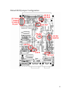
system. All controllers have the first 5 slots assigned as follows…
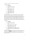
Slot Assignment
0 Power supply
1 Reserved for future expansion
2 Reserved for future expansion
3 CPU
4 Radio control board - port 0
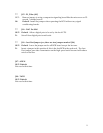
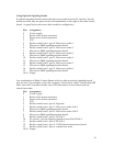
Radio Control Boards are installed starting in slot 4. Every radio requires a radio control
board. Radio Control Boards must be plugged into the backplane next to each other and
are named port 0 through port 7. There can be NO gaps between boards after port 0.


