


Section 2: Installation & Programming
21822666 2-103
Amplifier Factory Load
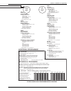
The AUDIO/VIDEO CONTROLLER has many programming options. For your convenience, service mode menu
item 95 restores the amplifier programming to factory settings.
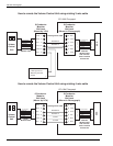
Other Configurations
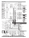
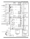
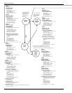
All the programming options and RCA jacks are covered in the audio block diagram, audio programming block
diagram, and the menu and command descriptions. Many configurations are possible to satisfy your imagination and
the location audio/video requirements.
If you have any questions, call the Rowe customer service department.
Summary of Audio/Video Controller Features and Flow – Front to Back
(ref: Audio Block Diagram)
• RCA jacks for Front End inputs
• Jacks marked CD/Stereo Mechanism, Stereo A (BGM), Stereo B, Mono C (BGM)
• AVC corrects Front End signal for varying recording levels
• RCA jacks for Left and Right AUXILIARY OUT with AVC and PAGING
• Left and Right channels split into 4 channels
• Left channel becomes channel 1 and channel 3
• Right channel becomes channel 2 and channel 4
• Channels 1, 2, 3, and 4 are equalized. Each channel has its own 5-band equalizer.
• RCA jacks for connecting external sound processor, other sound systems, etc.
• Jacks marked EQUALIZER OUT, and CH1 through CH4 INPUT
• RCA jacks for connecting AUX inputs
• Volume control for Channels 1, 2, 3, and 4. Each channel can be linked or separate
• Microphones
• 3 microphones can be connected and used simultaneously
• ¼-inch jacks for balanced and unbalanced microphones, and headers for Rowe microphones
• Each microphone can be routed to any or all 6 outputs (AUX L, AUX R, CH1, CH2, CH3, CH4)
• Microphones can be used for paging and/or karaoke
• RCA jacks and video and audio relays for video CD’s, karaoke, and location A/V (TV’s, etc.)
• Jacks marked AUDIO SWITCH and VIDEO SWITCH
• RCA jacks for connecting external sound processor, other sound systems, etc.
• Jacks marked:
• CH1 NON-INVERT SIGNAL, CH1 INVERT SIGNAL OUTPUT, CH1 SIGNAL OUTPUT
• CH2 OUTPUT, CH2 SIGNAL OUTPUT
• CH3 NON-INVERT SIGNAL, CH3 INVERT SIGNAL OUTPUT, CH3 SIGNAL OUTPUT
• CH4 OUTPUT, CH4 SIGNAL OUTPUT