


6 7
English
RA‑1520 Stereo Integrated Amplifier
6 7
English
RA‑1520 Stereo Integrated Amplifier
About Rotel
Our story began nearly 50 years ago. Over the decades, we have
received hundreds of awards for our products and satisfied hundreds of
thousands of people who take their entertainment seriously - like you!
Rotel was founded by a family whose passionate interest in music led
them to manufacture high-fidelity components of uncompromising quality.
Through the years, that passion has remained undiminished and the
family goal of providing exceptional value for audiophiles and music
lovers, regardless of their budget, is shared by all Rotel employees.
Rotel’s engineers work as a close team, listening to, and fine tuning,
each new product until it reaches their exacting musical standards. They
are free to choose components from around the world in order to make
that product the best they can. You are likely to find capacitors from the
United Kingdom and Germany, semiconductors from Japan or the United
States, while toroidal power transformers are manufactured in Rotel’s
own factory.
We all have concerns about our environment. And, as more and more
electronics are produced and later discarded, it is especially important
for a manufacturer to do all it can to engineer products that have a
minimum negative impact on landfill sites and water tables.
At Rotel, we are proud to do our part. We have reduced the lead content
in our electronics by using special ROHS solder, while our new Class D
(not digital) amplifiers are up to five times more efficient than our legacy
designs and still deliver power and performance. These products run
cool, give minimum wasted energy, are good for the environment and
give better sound too.
Finally, we have printed this manual on recycled paper stock.
While we understand that these are small first steps, they are still
important ones. And we continue to pursue new methods and materials
for a cleaner and greener manufacturing process. All of us at Rotel thank
you for buying this product. We are sure it will bring you many years of
enjoyment.
A Word About Watts
This amplifier’s power output is quoted as 60 watts for each channel,
when both channels are operating together at full power. Rotel has
chosen to specify the power output in this way because, in Rotel’s
experience, it gives the truest value of the receiver or amplifier’s power
capability.
When comparing specifications for different products, you should be
aware that power output is often specified in other ways, so you may
not be comparing like with like. For example, the power output may
be quoted with only one channel operating, giving a higher maximum
figure.
A loudspeaker’s impedance rating indicates the electrical resistance or
load it offers when connected to the amplifier, usually 8 ohms or 4 ohms.
The lower the impedance, the more power the speaker will need. In
effect, a 4 ohm speaker will require twice as much power as an 8 ohm
speaker.
Contents
Important Safety Instructions .......................................2
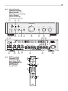
Figure 1: Controls and Connections 3
Figure 2: RR‑AT94 Remote Control 3
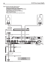
Figure 3: Signal Input and Speaker Output Connections 4
Important notes 5
About Rotel ....................................................6
A Word About Watts . . . . . . . . . . . . . . . . . . . . . . . . . . . . . . . . . . . . . . . . . . . . . 6
Getting Started . . . . . . . . . . . . . . . . . . . . . . . . . . . . . . . . . . . . . . . . . . . . . . . . . 7
A Few Precautions 7
Placement 7
Cables 7
Remote Control .................................................7
Audio Controls ABCE 7
CD Functions DG 7
DVD Functions G 7
Tuner Functions DF 7
Remote Sensor 3 8
Remote Control Batteries 8
External Remote In Connection r 8
IR Out Connection t 8
Speaker Outputs ................................................8
Speaker Wire Selection 8
Polarity and Phasing 8
Speaker Wire Connection [] 8
Input Signal Connections ..........................................9
Phono Input e and Ground Connection w 9
Line Level Inputs u 9
Recorder Connections io 9
Media Player Input 4 9
Preamp Outputs p 9
AC Power and Control ............................................9
AC Power Input \ 9
Power Switch and Power Indicator 1 9
12V Trigger Connection y 9
Audio Controls .................................................10
VOLUME Control 0C 10
BALANCE Control - 10
BASS and TREBLE Tone Controls 79 10
TONE On/Off 8 10
LISTENING Selector q 10
RECORDING Selector = 10
MUTE Button A 10
PHONES Output 5 10
SPEAKERS Selector 6 10
Protection Circuit . . . . . . . . . . . . . . . . . . . . . . . . . . . . . . . . . . . . . . . . . . . . . . . 10
Protection Indicator 2 10
Troubleshooting . . . . . . . . . . . . . . . . . . . . . . . . . . . . . . . . . . . . . . . . . . . . . . . . 11
Front Panel Power Indicator Is Not Lit 11
Fuse replacement 11
No Sound 11
Protection Indicator Is Lit 11
Remote Control Code Conflicts 11
Resetting The IR Code 11
Specifications ..................................................11