Applications Engineering
7.0 System Operation & Limitations
The RZB-ZMD16C-ZDK provides sophisticated debugging features at a low cost, but it does have some
limitations when used with the debugger and ICD. Section 6.1 introduces the kernel (ROM monitor)
program and its purpose. The limitations when this kernel is running with the user program are listed in
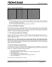
. Table 7-1
Table 7-1: System Limitations when Debugging
Item Please Refer To
7.2
7.3
7.4
User Limitations
7.5
7.6
Debugger Limitations
7.7
Pin and Peripheral Limitations
7.2. Pin and Peripheral Limitations
Memory Map
7.3. Memory Map
Register Operation Limitations
Limitations on Interrupts - Vectors that Reside in the Hardware
Vector Table
Stop or Wait Mode Limitations
User Program’s Real-Time Capability
7.1. Kernel (ROM Monitor) Introduction
During debug, a small program called a kernel is uploaded to the M16C/28. The kernel communicates
with HEW through the ICD regarding MCU status during user code debugging operations.
There are no special steps required in the user program to make use of the ICD. The operation of the
kernel is transparent to the user, but there are some limitations. These are discussed from section 7.2
onward.
After starting a HEW debug session, the ICD uploads the kernel to the M16C/28 if it does not exist (e.g. a
blank device or a device that was programmed with the FoUSB Programmer). After downloading the
kernel, the M16C/28 is ready to download user code.
Connecting the ICD without starting HEW will not affect the signal lines connected between the ICD and
the M16C/28; the ICD keeps the signal lines in high-impedance state. The ICD only drives the pins after
HEW or the FoUSB Programmer attempts to connect.
After completing program debug and verification with HEW, you can create an image of your code in Intel
(.hex) or Motorola (.mot) file formats. This image can be programmed into the M16C/28 using the FoUSB
Programmer. This procedure erases the kernel and leaves only the user program.
SIO/UART1 pins are used for communication between the M16C/28 kernel on the RZB-ZMD16C-ZDK
board and HEW through the ICD. Do not connect these pins to any other circuit, as UART1 cannot be
used in the user program while using the Debugger. For details, please see the RTA-FoUSB-MON (ICD)
User’s Manual on Target M16C ROM Monitor Resources or related ICD application notes.
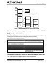
The amount and locations of memory used by the kernel on the RZB-ZMD16C-ZDK board’s M16C/28
MCU are shown in . Figure 7-1
RZB-ZMD16C-ZDK User’s Manual Rev 1.2 17/ 33 August 2006


