


Applications Engineering
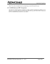
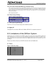
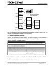
5.2. RZB-ZMD16C-ZDK Board Block Diagram
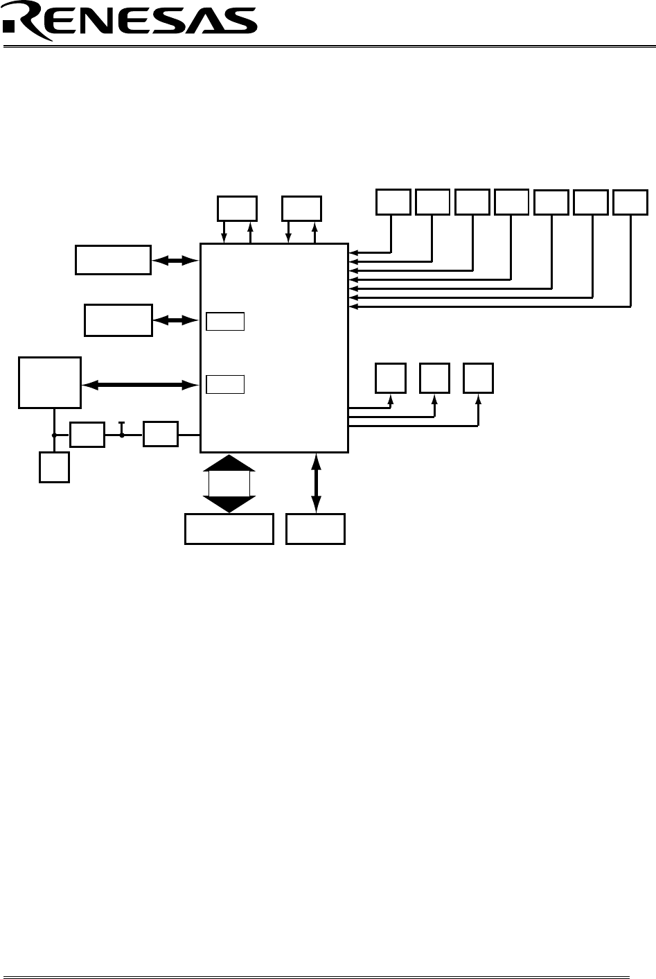
The RZB-ZMD16C-ZDK board incorporates an M30280FAHP (80-pin QFP) from the M16C/28 group of
microcontrollers designated as U4. Figure 5-2 shows the RZB-ZMD16C-ZDK block diagram.
S1 S2 S3 S4 R3 RT1 R44
P10_4 P10_5 P10_6 Reset AN2 AN1 AN0
Y1
10MHz
Y2
32kHz
Xin Xout XCin XCout
U4
M30280FAHP
MCU
D1 D2 D3
Red
LED
Yellow
LED
Green
LED
P3_4 P3_5 P3_6
J1, J2, J3, J4
Headers
Ports
JP1
Vcc
Vcc
MCU Power
for Icc
Measurements
8 characters
x 2 lines LCD
P0_0...6
JP2
RS232
Transceiver
UART 2
UART 1
D4
Red
Power LED
RS232
Power
J7
ICD Header
ZigBee
RF
Figure 5-2: RZB-ZMD16C-ZDK Block Diagram
5.3. M16C/28 Group of MCUs
The M3028x group of 16-bit single-chip, flash microcontrollers (MCU) is part of the M16C/60 series CPU
core. The hardware and software manuals for the M16C/28 group of microcontrollers can be found under
C:\Renesas\RZB_ZMD16C_ZDK\Docs folder on your PC or from the Start menu (Start > Programs >
Renesas > RZB_ZMD16C_ZDK > All Manuals and Documents) after ZDK software installation.
5.4. RZB-ZMD16C-ZDK Board Jumper Configuration
5.4.1. JP1: MCU (U4) Power
JP1 is used to connect the Vcc pins of the M16C/28 MCU to the 3.3V supply of the board. It can be
used to measure current/power consumption of the MCU during various modes of operation. For
normal operations, JP1 must be shorted.
JP1 is shorted by default.
RZB-ZMD16C-ZDK User’s Manual Rev 1.2 12/ 33 August 2006