


28
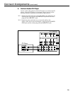
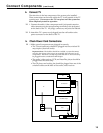
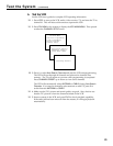
Optional Connection Diagram
IN FROM
ANTENNA
OUT TO TV
CH
3 4
OUTPUT
AUDIO
R
INPUT
VIDEO
L
MONO
Splitter
Option 1
Cable Box
Option 2
Cable Box
AUDIO
R/
MONO
SELECT OUTHI-FI OUT
R/
MONO
INPUT 1
R/
MONO
INPUT 2
L
L
L
S-VIDEO
VIDEO
INPUT SELECT
OUT21
CONVERTER
ANT B
ANT A
CABLE/ANTENNA
L
R
+
–
–
+
FRONT
L
R
+
–
–
+
SURROUND
IN FROM
ANT
OR
CABLE
CENTER
+
–
VCR
Jack Panel
Extension Cable
Input
Set 1 Set 2
SUBWOOFER
OUT
IN FROM
DSS ANT
➤
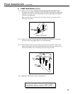
Connection for System Requiring a Cable Box
If the cable system requires a cable box, connect it to the splitter as shown.
Additional cables may be required.
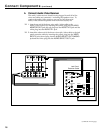
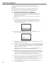
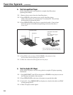
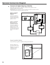
Important Note: If the cable box is remote controllable, the VCR may be able to control
it. Place the cable box on top of the VCR as shown below.
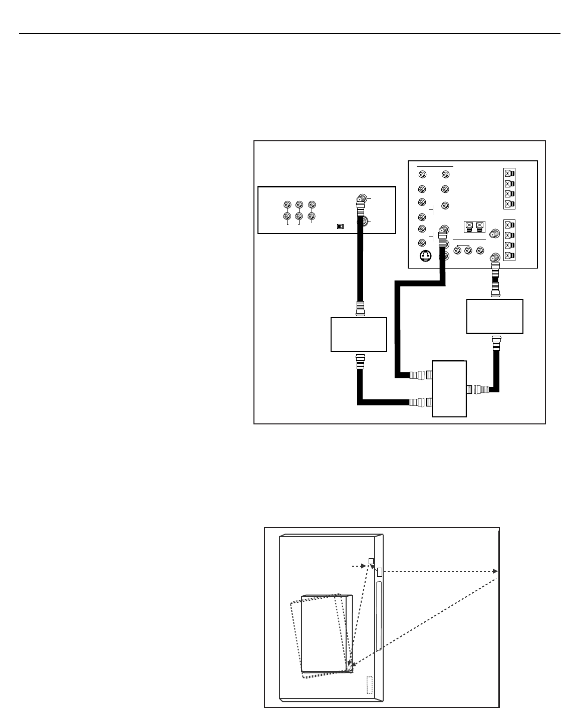
Remote Controllable Cable Box
See the VCR user’s guide for details on setting up the cable box.
VCR's Signal
VCR's Signal
Transmitters
Front of VCR
Cable
Box
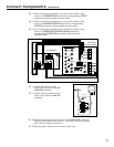
Option 1: Cable Box
Required for All
Channels
Connect the cable box
between the jack panel
extension cable and the
splitter as shown.
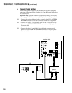
Option 2: Cable Box
Required Only for
Scrambled Channels
Connect the cable box
between the VCR and
splitter as shown. All
scrambled channels will
be viewed through the
VCR.
Place the cable box on
top of the VCR as shown.
Caution: Be careful not
to block the VCR’s
ventilation holes.