


17
Connect Components
(continued)
AUDIO
R/
MONO
SELECT OUTHI-FI OUT
R/
MONO
INPUT 1
R/
MONO
INPUT 2
L
L
L
S-VIDEO
VIDEO
INPUT SELECT
OUT21
CONVERTER
ANT B
ANT A
CABLE/ANTENNA
L
R
+
–
–
+
FRONT
L
R
+
–
–
+
SURROUND
IN FROM
ANT
OR
CABLE
CENTER
+
–
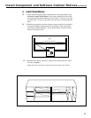
Jack Panel
Extension Cable
SWITCHED TOTAL 100W, 0.8A MAX
AC OUTLETS
120V 60H
AC 120V 60H
L
L
L
R
R R
Center
+
–
+
–
+
+ +
+
–
+
–
SWITCHED TOTAL 100W, 0.8A MAX
AC OUTLETS
120V 60H
AC 120V 60H
L
L
L
R
R R
Main Center
–
–
Rear
Front
–
SPEAKERS
(8 )
SURROUND SPEAKERS
(8 )
A/V Receiver
SUBWOOFER
OUT
IN FROM
DSS ANT
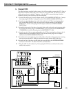
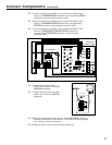
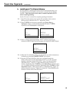
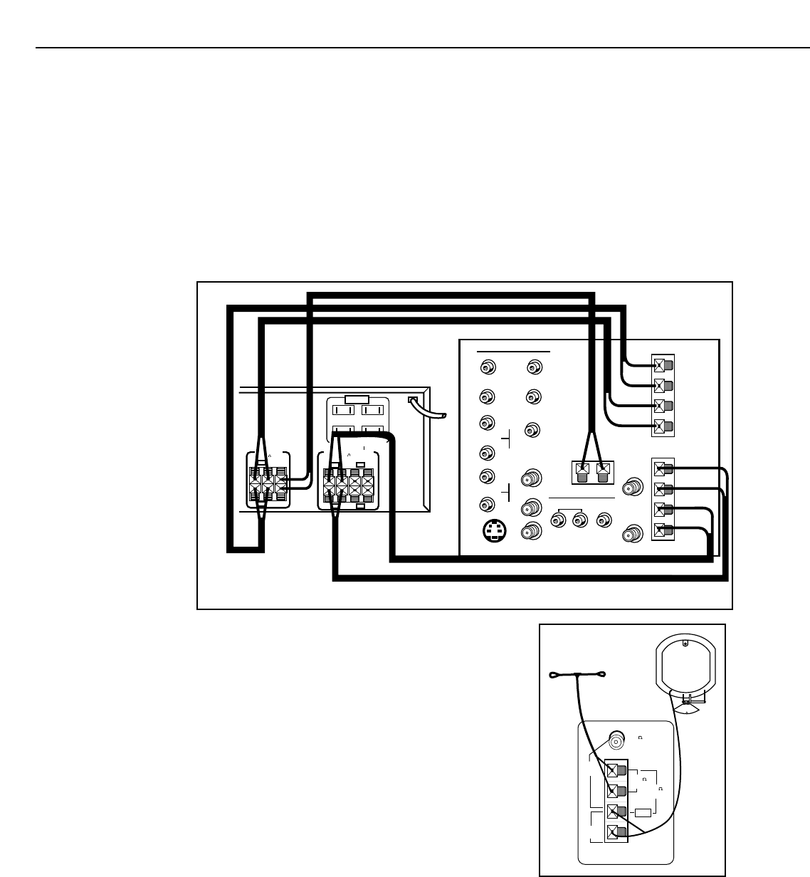
❑ 3.Use at least 3 feet of speaker wire to connect the audio/video
receiver’s SPEAKERS MAIN terminals to corresponding FRONT
terminals on the jack panel extension cable.
❑ 4.Use at least 3 feet of speaker wire to connect the audio/video
receiver’s SPEAKERS CENTER terminals to corresponding
CENTER terminals on the jack panel extension cable.
❑ 5.Use at least 3 feet of speaker wire to connect the audio/video
receiver’s SURROUND SPEAKERS REAR terminals to
corresponding SURROUND terminals on the jack panel
extension cable.
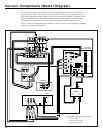
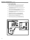
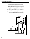
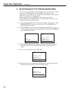
❑ 6.Attach FM antenna to the
audio/video receiver’s FM ANT-
300Ω BAL terminals.
❑ 7.Attach AM loop antenna to the
audio/video receiver’s AM ANT
terminals.
300
BAL
75
UNBAL
75
UNBAL
GND
AM
ANT
FM
ANT
AM Antenna
FM Antenna
A/V Receiver
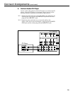
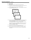
❑ 8.Plug the heat dissipation fan into one of the SWITCHED outlets on
the back of the audio/video receiver. This allows the fan to operate
only when the system is turned on.
❑ 9.Plug the audio/video receiver into the outlet strip.