


12
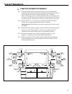
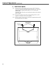
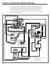
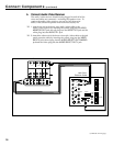
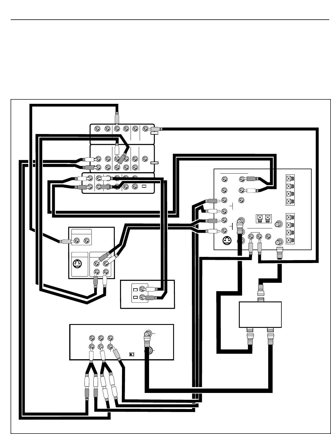
Connect Components (Master Diagram)
IN FROM
ANTENNA
OUT TO TV
CH
3 4
OUTPUT
AUDIO
R
INPUT
VIDEO
L
MONO
L
R
AUDIO OUT
1/L
1
2
2/R
1
2
S-VIDEO
OUT
VIDEO OUT
LINE OUT
VCR 1 VCR 2/LD DSS MONITOR
OUT
VCR 1 DSSVCR 2/LD
IN
OUT IN OUT
IN OUT IN OUT
IN OUT IN OUT
TV CD TAPE 1/DAT TAPE 2/MONITOR
VIDEO
AUDIO
AUDIO
R
L
AUDIO
R/
MONO
SELECT OUTHI-FI OUT
R/
MONO
INPUT 1
R/
MONO
INPUT 2
L
L
L
S-VIDEO
VIDEO
INPUT SELECT
OUT21
CONVERTER
ANT B
ANT A
CABLE/ANTENNA
L
R
+
–
–
+
FRONT
L
R
+
–
–
+
SURROUND
IN FROM
ANT
OR
CABLE
IN FROM
DSS ANT
CENTER
+
–
VCR
LaserDisc Player
Jack Panel
Extension Cable
A/V Receiver
L
R
R
L
V
SUB WOOFER
OUT
SUBWOOFER
OUT
L
R
CD Player
R
L
L
R
L
L
R
L
L
R
L
R
L
R
Splitter
Input
Set 1 Set 2
V
R
R
L
V
L
R
R
V
L
V
V
L
R
L
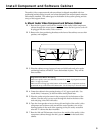
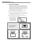
Audio/Video Cable and Jack Color Codes
• Yellow = Video
• Red = Right Audio (R)
• White = Left Audio (L)
Connections need to be made between the components and the front side of the jack
panel extension cable. To make access easier while connecting the components, you
may want to keep the audio/video receiver out in front of the cabinet. Position the CD
player, LaserDisc player, and VCR toward the front of their shelves. After all of the
connections are completed, move all of the components into their proper places.
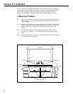
The TV is the last component to be installed. Move it as close to the opening as possible
until the system has been tested.