


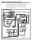

Connect Components
(continued)
IN FROM
ANTENNA
OUT TO TV
CH
3 4
OUTPUT
AUDIO
R
INPUT
VIDEO
L
MONO
Splitter
AUDIO
R/
MONO
SELECT OUTHI-FI OUT
R/
MONO
INPUT 1
R/
MONO
INPUT 2
L
L
L
S-VIDEO
VIDEO
INPUT SELECT
OUT21
CONVERTER
ANT B
ANT A
CABLE/ANTENNA
L
R
+
–
–
+
FRONT
L
R
+
–
–
+
SURROUND
IN FROM
ANT
OR
CABLE
CENTER
+
–
VCR
Jack Panel
Extension Cable
Input
Set 1 Set 2
SUBWOOFER
OUT
IN FROM
DSS ANT
➤
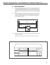
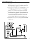
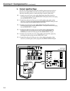
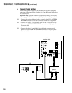
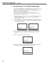
Connect Signal Splitter
The two-way splitter supplied in the accessory kit is used to complete
connection of the components. Use the two 6-inch RF coaxial cables from
the accessory kit.
Important Note: Optional connections for systems including a cable box are
shown on page 28. Additional cables may be required for connecting a cable box.
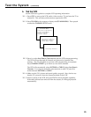
❑ 1.Connect the coaxial cable previously attached to the VCR’s IN FROM
ANTENNA connector to the Set 2 connector on the two-way splitter.
❑ 2.Connect one of the 6” coaxial cables from the Set 1 connector on the
splitter to the CABLE/ANTENNA ANT A connector on the jack panel
extension cable.
❑ 3.Connect the other 6” coaxial cable from the Input connector on the
splitter to the IN FROM ANT OR CABLE connector on the jack panel
extension cable.
18