


This quick start section is for those users who want to get up and running with the DSP-3 and Signal Manager
software as quickly as possible. It is in no way a substitute for reviewing the contents of the entire hardware
manual. It is intended for people familiar with the equipment discussed and should be followed up with a review
of the manual and the software help file.
This is the same material covered in the Signal Manager software help file, only presented on paper so that you
may “get right to it”.
1 TURN THE EQUIPMENT OFF & INSTALL THE HARDWARE
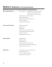
If you are using the DSP-3 with.......
QSC Powerlight2, CX, DCA 2-channel, 2-RU am-
plifiers (or later direct-mount applications)
QSC 4-channel CX & DCA amplifiers (or later
models with full-featured DataPort that do not
support direct mounting of the DSP-3)
QSC Powerlight 6.0 or Powerlight 9.0
QSC Powerlight, all except 6.0 & 9.0
a non-DataPort amplifier (QSC USA, PLX or non-
QSC models
Then you need to.....
Mount the DSP-3 to the amplifier by plugging it into the amp’s DataPort and
securing it with the supplied hardware. External power may be required for
older models (see Appendix).
Mount the DSP-3 remotely and connect a QSC DataPort cable between the
amplifier’s DataPort and the DSP-3’s “backside” DataPort. External power
may be required for older models (see top of page 2).
Mount the DSP-3 remotely and connect a MODIFIED QSC DataPort cable
(male-to-female cable with pin #9 removed) between the amplifier’s DataPort
and the DSP-3’s “backside” DataPort. Connect the external power supply to
the DSP-3’s EXTERNAL POWER jack.
Mount the DSP-3 remotely and connect a QSC DataPort cable (male-to-
female) between the amplifier’s DataPort and the DSP-3’s “backside” DataPort.
Connect the external power supply to the DSP-3’s EXTERNAL POWER jack.
Mount the DSP-3 remotely. Connect the DSP-3’s CHANNEL 1 OUTPUT and
CHANNEL 2 OUTPUT to the appropriate amplifier inputs (see p.18 for
pinouts). Connect the external power supply to the DSP-3’s EXTERNAL
POWER jack.
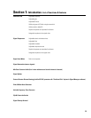
2 CONNECT THE COMPUTER TO THE DSP-3
Use a 9-pin serial data cable to connect the DSP-3’s RS-232 connector to the computer’s available COM port (the 9-pin serial port
connector on the back of the PC). COM1 through COM4 are usable with the Signal Manager software. COM1 is the default port in Signal
Manager; use COM1 for your connection if it is available. If not, you will need to select the appropriate COM port in the Signal Manager
program
after
you install it in step 5.
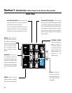
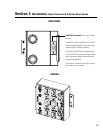
Section 1: Introduction- Quick Start
7