


Section 5: Appendix- DataPort Pinout
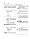
Description of Encode Signals
encode 1 Bridge mode & power detect
encode 2 Temperature, channel 1
encode 3 Standby mode detect
encode 4 Temperature, channel 2
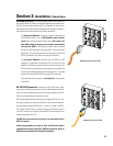
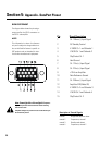
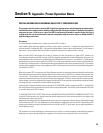
DATA PORT PINOUT
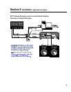
The diagram below shows the pin assign-
ments used for the HD-15 connectors on
the DSP-3 and amplifier.
NOTE!
This information is shown for reference
only and is subject to change without no-
tice as the DataPort feature is specific to
QSC products and not intended for inter-
face to other manufacturer’s equipment.
30
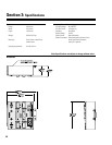
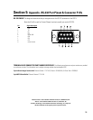
Note: Powerlight 6.0 and Powerlight 9.0 amplifiers
require that pin #9 be removed from the remote mounting
interconnect cable.
Amplifier damage may result from use of cable that has pin
#9 connections present.
Pin Signal Description
1 Ch. 1 Minus (-) Input Signal
2 AC Standby Control
3 V- MON Ch. 1 and Subcode 1
4 I- MON Ch. 1 and Subcode 2
5 Clip/Protect Ch. 1
6 Hard Ground
7 Ch. 1 Plus (+) Input Signal
8 Ch. 2 Plus (+) Input Signal
9 +15V from Amplifier
10 Data Reference Ground
11 Ch. 2 Minus (-) Input Signal
12 Amplifier IDR (Model ID)
13 V- MON Ch. 2 and Subcode 3
14 I- MON Ch. 2 and Subcode 4
15 Clip/Protect Ch. 2