


Section 4: Architect’s and Engineer’s Specifications
The Digital Signal Processor (DSP) shall provide two independent
channels of DSP for signal delivery to QSC DataPort equipped
power amplifiers. The processing shall be distributed with the DSP
module mounted directly to the rear of the power amplifiers.
Output Peak Limiter—For each audio channel, the DSP shall
provide a peak limiter that is assignable anywhere in the
signal chain and can be switched on or off. The limiter shall
provide the following adjustments:
Gain
Threshold
Attack time
Release time
High- and Low-Pass Crossovers—For each channel of audio,
the DSP will provide high-pass and low-pass crossovers
that are assignable anywhere in the audio chain. The
crossovers must be capable of being switched in or out
of the signal chain. The DSP shall provide the following
crossover responses:
Butterworth (6,12,18,24 dB per octave slope)
Bessel (6,12,18,24 dB per octave slope)
Linkwitz-Riley (12 & 24 dB per octave slope)
High- and Low-Pass Shelf Filters—For each audio channel, the
DSP shall provide high-pass and low-pass shelf filters
that are assignable anywhere in the audio chain. The
shelf filters must be capable of being switched in or out
of the signal chain. The DSP shall provide the following
shelf filter adjustments:
Variable corner frequency
Variable gain
Variable slope
Compressor-- The DSP shall provide a signal compressor that is
assignable anywhere in the signal chain. It shall have adjustable
threshold, attack time, release time, and compression ratio.
29
Contact Closure I/O—The DSP shall provide a trigger input
usable for contact-closure (or other) purpose which shall
be CMOS & TTL signal compatible.
Power Supply—The DSP shall be provided power through its
DataPort connection to QSC amplifiers. For older ampli-
fiers or non-QSC amplifiers, a coaxial power jack will be
provided on the DSP for connection to an external power
source. Power required shall be +15 VDC at 300 mA
(max.).
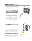
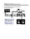
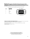
Amplifier Interface—The DSP shall attach directly to the rear of
each power amplifier. The DSP’s interface to each power
amplifier Data Port shall be via an HD-15 connector. This
interface shall transmit two amplifier input audio signals
as well as all control and monitoring signals. Special
signal conditioning and grounding techniques shall be
used in this interface to ensure negligible levels of noise
and crosstalk. For non-DataPort amplifiers, there shall be
mounting and interface options provided for operating
with the DSP.
Amplifier Output Monitoring—When used with QSC DataPort
amplifiers, the DSP shall provide clipping and protect
status detection at the amplifier’s output terminals.
Noise & Tone Generation-- The DSP shall provide pink and
white noise generation capability. It shall also provide for
tone generation.
Presets— The DSP shall be capable of storing at least 8 preset
configurations. The control software shall provide man-
agement of these presets.
General—All audio inputs and outputs shall be balanced with a
nominal input level of +4 dBu and maximum level of +21
dBu. Input connectors shall be of the “Phoenix” detach-
able terminal block type.
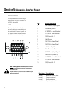
Control— The DSP shall be configurable via RS-232 or via a
networked DataPort connection.
The Digital Signal Processor shall be the QSC DSP-3.