


38
Section 6: Appendix- DataPort Pin-out & Connector P-N’s
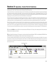
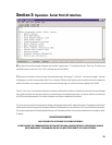
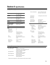
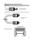
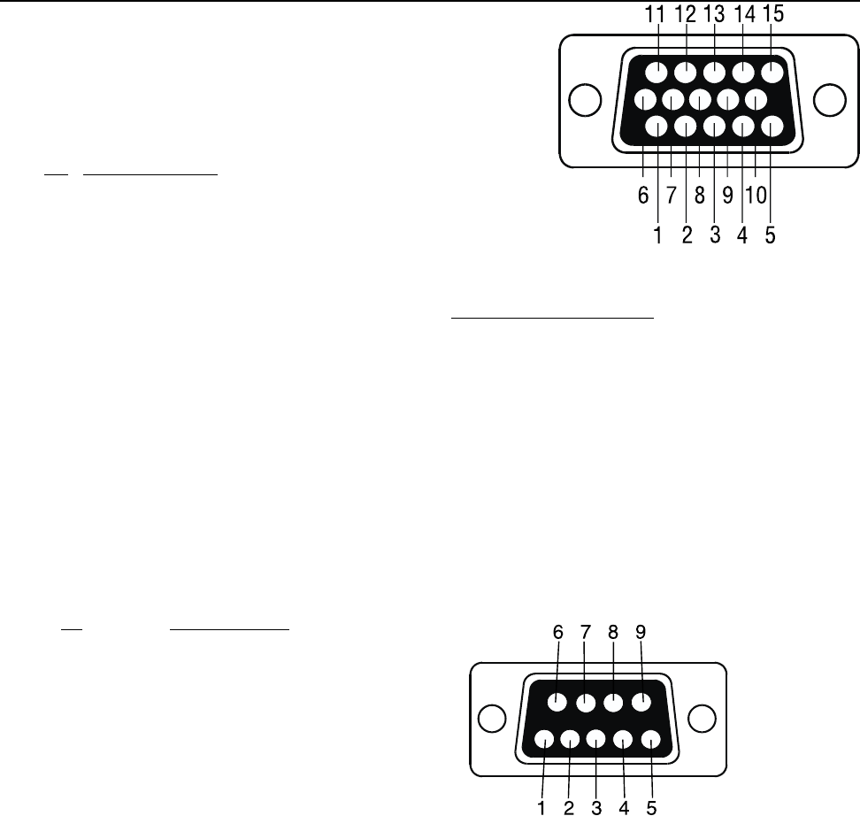
DATA PORT PINOUT: The diagram to the right shows the pin assignments
used for the HD-15 connectors on the CM16a and amplifier.
NOTE!
This information is shown for reference only and is subject to change without
notice as the DataPort feature is specific to QSC products and not intended for interface
to other manufacturer’s equipment.
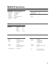
TERMINAL BLOCK CONNECTOR PART NUMBER REFERENCE- The following manufacturers and part numbers are provided as a
reference to users. The information here is subject to change without the knowledge of QSC.
2 pin: Phoenix Contact - 17 57 01 9; Riacon - 31249102-6; On-Shore Tech - EDZ950/2
3 pin: Phoenix Contact - 17 57 02 2; Riacon - 31249103-6; On-Shore Tech - EDZ950/3
5 pin: Phoenix Contact - 17 57 04 8; Riacon - 31249105-6; On-Shore Tech - EDZ950/5
Strain Relief 3 pin: Phoenix Contact 17 76 16 8
Strain Relief 5 pin: Phoenix Contact 17 76 14 2
WEBSITE reference-
Phoenix-
phoenixcon.com
Riacon-
riaelectronic.com
On-Shore-
on-shore.com
Pin Signal Description
1 Audio to channel 1 (+)
2 Standby control
3 V
MON
channel 1 plus encode 1
4 I
MON
channel 1 plus encode 2
5 Clip/protect channel 1
6 Hard ground
7 Audio to channel 1 (ground)
8 Audio to channel 2 (ground)
9 unused for CM16a, +15V on certain amp’s
10 Amp reference ground
11 Audio to channel 2 (+)
12 Amp IDR (model ID)
13 V
MON
channel 2 plus encode 3
14 I
MON
channel 2 plus encode 4
15 Clip/protect channel 2
Description Encode Signals
encode 1 Bridge mode & power detect
encode 2 Temperature, channel 1
encode 3 Standby mode detect
encode 4 Temperature, channel 2
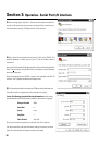
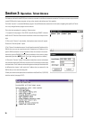
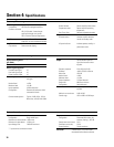
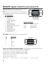
RS-232 PINOUT: The diagram below shows the pin assignments for RS-232.
Pin Signal Description
1 DCD
2 RX
3 TX
4 DTR
5 Signal GND
6 DSR
7 RTS
8 CTS
9 not used