


36
SECTION 5: ARCHITECT’S AND ENGINEER’S SPECIFICATIONS
The Amplifier Network Monitor shall provide input, output,
and status control for DataPort equipped QSC power ampli-
fiers in an Ethernet-TCP/IP based network audio system.
Sixteen independent channels shall be provided, grouped in
pairs.
Amplifier Input Control and Monitoring—For each of the
sixteen power amplifier input signals, the CM16a
shall provide level, mute and polarity control, pre and
post fade signal level metering and audio monitoring,
and selectable 1Vrms or 3Vrms input sensitivity. The
Amplifier Network Monitor shall provide a page
input, separate from the normal program inputs,
whose signal may preempt the program signal of any
or all of the sixteen program channels. This input shall
have selectable 1V or 3V sensitivity.
Amplifier Output Monitoring—For each of the sixteen
power amplifier outputs, the Amplifier Network
Monitor shall provide clipping detection, short and
open circuit detection, voltage and current meter-
ing, and audio monitoring of the voltage signal.
Amplifier Management—For each of the eight DataPort
connections, the Amplifier Network Monitor shall
provide AC standby/operate mode control, AC
power state indication, temperature metering, load
status, and protect status detection.
Audio Monitoring Chain—For each of the sixteen pro-
gram channels, the Amplifier Network Monitor
shall provide three monitor points as follows: (1)
pre-fader control, (2) post-fader control, or (3) power
amplifier output. A channel’s monitor output may
be selected from one of these three signals, or it
may be switched off. The signal at the Amplifier
Network Monitor’s monitor output connector shall
be the sum of the signal at its monitor input connec-
tor and four selected (cont’d. next column-->)
channel monitor signals. A monitor gain control
shall be provided for each monitor tap point to
adjust the individual levels of the channel monitor
signals prior to their being mixed with the monitor
input signal.
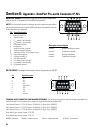
Contact Closure I/O—The Amplifier Network Monitor shall
provide a trigger contact-closure sense input which
shall also be CMOS & TTL signal compatible, and
one dry-contact floating SPDT relay output.
Data Network—All Amplifier Network Monitor functions
shall be controlled and monitored via a 10BASE-T
Ethernet digital control network using the IP trans-
port protocol and the QSControl monitoring appli-
cation protocol. Rear-panel connection shall be
provided for 10BASE-T Ethernet. Other than the AC
power switch, the Amplifier Network Monitor shall
have no manual controls.
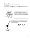
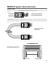
Amplifier Interface—The Amplifier Netrwork Monitor’s
interface to each power amplifier Data Port shall be
via an HD-15 connector. The amplifier interface
shall use a standard personal computer Video Graph-
ics Adapter (VGA) CRT monitor cable. This interface
shall transmit two amplifier input audio signals as
well as all control and monitoring signals. Special
signal conditioning and grounding techniques shall
be used in this interface to ensure negligible levels
of noise and crosstalk.
General—All audio inputs and outputs shall be balanced
with a nominal input level of +4 dBu and maximum
level of +21 dBu. Input connectors shall be of the
“Phoenix” detachable terminal strip type.
The Amplifier Network Monitor shall be the QSC CM16a.