TABLE OF CONTENTS: CM16a Amplifier Network Monitor
Section 1: INTRODUCTION Overview...................................................................................................5
Physical Characteristics & Layout........................................................6
List of Functions & Features...................................................................8
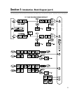
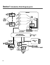
Block Diagram.........................................................................................9
Detailed Description of Functions.......................................................11
Network Description.............................................................................14
Network Examples................................................................................15
Section 2: INSTALLATION Basics: Unpacking............................................................17
What is Included.................................................17
Location Considerations....................................17
Mounting the CM16a..........................................17
Connecting: AC Power..............................................................18
Audio Inputs.........................................................19
Page Input............................................................20
RLY/TRG Input......................................................20
RLY Output............................................................20
Monitor Chain In/Out..........................................20
10
BASE-T Input/Output........................................21
RS-232 Port...........................................................21
Amplifiers.............................................................21
Rear Panel Detailed Illustration & Hookup Example........................22
Section 3: OPERATION General: Amp Setup, Network Setup...............................24
LED Behavior........................................................25
BYPASS Switch Usage......................................25
Serial Port Interface...........................................27
Telnet Access......................................................30
Fuse Replacement...............................................31
Section 4: SPECIFICATIONS.......................................................................................................................................32
Section 5: ARCHITECT’S & ENGINEER’S SPECIFICATION..................................................................................36
Section 6: APPENDIX Ethernet Cable & RS-232 Pinouts ........................................................37
DataPort Pinout and “Phoenix”-type Connector Part Numbers......38
Section 7: QSC INFORMATION How to Contact QSC Audio Products..................................................39
3


