


Section 2: Installation- Connections
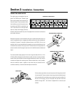
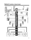
CONNECTING AUDIO INPUTS
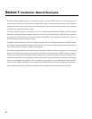
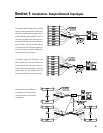
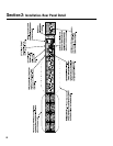
The audio inputs are located on the rear
panel. The CM16a uses “Phoenix”-type
(Euro-style) terminal block connectors for
the audio inputs. These connectors allow
the installer to pre-wire the input termina-
tions before the CM16a is installed in the
rack. It also allows for re-routing of audio
inputs by simply interchanging connector
locations without the need for any tools. See Appendix for connector manufacturer’s
part number reference.
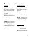
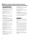
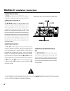
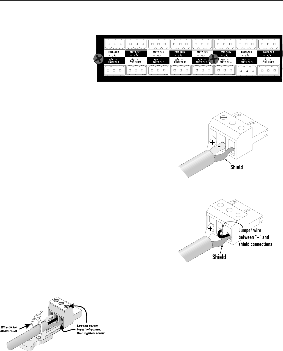
Balanced connection is recommended for all inputs. If unbalanced audio sources are
used, it is preferable to use an appropriate audio transformer (or other unbalanced-
to-balanced “converter”) to provide a balanced input to the CM16a. If this is not
possible, then it is recommended that the negative terminal and shield terminal be
connected to one another with a jumper wire. The illustrations to the right show the
proper connection of audio program input sources for both balanced and unbalanced
inputs.
The recommended stripping length for the wires is approximately 6 to 8 mm ( 1/4 to
5/16 inch). When stripping the audio cable, be careful not to nick or cut the conductor
strands. After each conductor has been stripped and dressed, insert it fully into the
connector and tighten the retaining screw. When stranded wire is used, carefully
twist the conductor strands together so that when they are inserted into the
connector assembly, no loose strands short adjacent terminals.
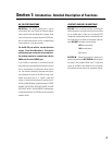
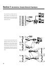
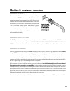
For heavy-duty input cables, the use of connectors with integral strain relief
is recommended. These connectors have a large plastic tab molded as part
of the assembly which provides an area to tape or tie-wrap the cable to. At
the time of this writing, only the 3-terminal with the strain relief was
available through QSC . See Section 6 (Appendix) for connector part
numbers.
BALANCED INPUT CONNECTION
UNBALANCED INPUT CONNECTION
STRAIN RELIEF
REAR PANEL- AUDIO INPUTS
19