


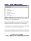

Section 3: Operation- LED Behavior & Bypass Switch Usage
BYPASS SWITCH USE
There are two distinctly different BYPASS modes.
The first mode is the “Oops, I forgot the computer” or system troubleshooting type of BYPASS. If you are unable to communicate with
the CM16a for any reason and you need to bypass the unit, it can be done with the push of a button instead of rewiring the system.
If the CM16a is powered-up and there is no host computer control (or the network is non-operational), the operational state (as saved in
Preset #0, the start-up preset) could prevent the audio from being supplied to the amplifiers. We have addressed this potentially disastrous
situation by providing a BYPASS (or “virtual-wire”) mode switch. The function of this switch is to put the CM16a into a known state of
operation. This “BYPASS” state routes all audio through the CM16a in a “virtual wire” mode (
1Vrms input sensitivity,
PAGE
input
disabled,
MUTE
disabled, 0 dB level, normal polarity
). This insures that audio can still be passed through the CM16a regardless of
network/computer issues.
(continued on next page)
25
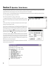
LED BEHAVIOR-
When the power is switched ON, all of the LED’s light briefly and then the PORT LED’s sequence through two patterns.
The LED’s then resume normal operation. The LED functions are described below.
POWER LED
- The power LED will illuminate whenever the power switch is in the POWER (ON) position.
DIAGNOSTIC LED
- This indicator first illuminates during the power-on self test of the CM16a, then should turn off. It will also illuminate
to indicate that the CM16a self-test has detected an unexpected event, such as a corrupted firmware update via TFTP or a memory boot
failure. This would typically be accompanied by a “fault code” displayed by the PORT CONNECTED indicators (described below). If the
DIAGNOSTIC LED remains illuminated, try resetting the CM16a by cycling power off and on once. Should the indication persist, contact
Technical Services for guidance.
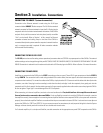
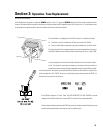
NETWORK STATUS LED’s
- For diagnostic purposes, there are three network status LED’s on the front and rear panels of the CM16a.
They are labeled RCV, XMT and LINK STATUS. Their locations are shown in the illustration at the start of the
Introduction
section. Their
functions are described below.
RCV- This LED lights up any time the CM16a receives data over the network.
XMT- This LED lights up whenever the CM16a transmits data over the network.
LINK STATUS- When lit, this LED indicates that the CM16a is connected to an operating Ethernet network.
If not lit, there is most likely a cabling problem between the CM16a and the hub or possibly a fault in the hub.
PORT CONNECTED LED’s-
These LED’s are labeled PORT A through PORT H on the front panel. The respective LED will illuminate
when functional connection has been made between the CM16a and an amplifier. The amplifier’s power does not have to be ON in order
for the LED to indicate successful connection. As mentioned above, these LED’s may also display specific “fault codes” if the CM16a detects
an internal failure in one of its associated self-test/diagnostic parameters. The “fault code” will be in the form of a specific sequence of
these LED’s being illuminated.