


User’s Manual of FGSW-2620VM / FGSW-2620PVM
75
The port identifier of the transmitting port.
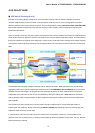
The switch sends BPDUs to communicate and construct the spanning-tree topology. All switches connected to the LAN on
which the packet is transmitted will receive the BPDU. BPDUs are not directly forwarded by the switch, but the receiving
switch uses the information in the frame to calculate a BPDU, and, if the topology changes, initiates a BPDU transmission.
The communication between switches via BPDUs results in the following:
One switch is elected as the root switch.
The shortest distance to the root switch is calculated for each switch.
A designated switch is selected. This is the switch closest to the root switch through which packets will be
forwarded to the root.
A port for each switch is selected. This is the port providing the best path from the switch to the root switch.
Ports included in the STP are selected.
Creating a Stable STP Topology
It is to make the root port a fastest link. If all switches have STP enabled with default settings, the switch with the lowest
MAC address in the network will become the root switch. By increasing the priority (lowering the priority number) of the best
switch, STP can be forced to select the best switch as the root switch.
When STP is enabled using the default parameters, the path between source and destination stations in a switched
network might not be ideal. For instance, connecting higher-speed links to a port that has a higher number than the current
root port can cause a root-port change.
STP Port States
The BPDUs take some time to pass through a network. This propagation delay can result in topology changes where a port
that transitioned directly from a Blocking state to a Forwarding state could create temporary data loops. Ports must wait for
new network topology information to propagate throughout the network before starting to forward packets. They must also
wait for the packet lifetime to expire for BPDU packets that were forwarded based on the old topology. The forward delay
timer is used to allow the network topology to stabilize after a topology change. In addition, STP specifies a series of states
a port must transition through to further ensure that a stable network topology is created after a topology change.
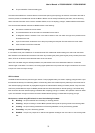
Each port on a switch using STP exists is in one of the following five states:
Blocking – the port is blocked from forwarding or receiving packets.
Listening – the port is waiting to receive BPDU packets that may tell the port to go back to the blocking state.
Learning – the port is adding addresses to its forwarding database, but not yet forwarding packets.
Forwarding – the port is forwarding packets.
Disabled – the port only responds to network management messages and must return to the blocking state
first.