


User’s Manual of FGSW-2620VM / FGSW-2620PVM
184
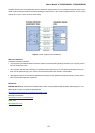
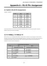
The standard cable, RJ-45 pin assignment
The standard RJ-45 receptacle/connector
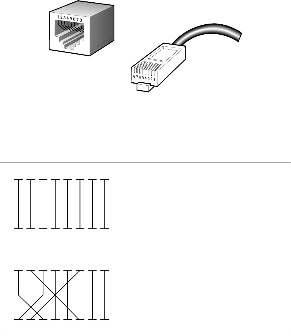
There are 8 wires on a standard UTP/STP cable and each wire is color-coded. The following shows the pin allocation and
color of straight cable and crossover cable connection:
Straight Cable SIDE 1 SIDE2
SIDE 1
12345678
12345678
SIDE 2
1 = White / Orange
2 = Orange
3 = White / Green
4 = Blue
5 = White / Blue
6 = Green
7 = White / Brown
8 = Brown
1 = White / Orange
2 = Orange
3 = White / Green
4 = Blue
5 = White / Blue
6 = Green
7 = White / Brown
8 = Brown
Straight Cable SIDE 1 SIDE2
SIDE 1
12345678
12345678
SIDE 2
1 = White / Orange
2 = Orange
3 = White / Green
4 = Blue
5 = White / Blue
6 = Green
7 = White / Brown
8 = Brown
1 = White / Orange
2 = Green
3 = White / Orange
4 = Blue
5 = White / Blue
6 = Orange
7 = White / Brown
8 = Brown
Figure A-1: Straight-Through and Crossover Cable
Please make sure your connected cables are with same pin assignment and color as above picture before deploying the
cables into your network.