


User’s Manual of FGSW-2620VM / FGSW-2620PVM
19
2. INSTALLATION
This section describes the hardware features and installation of the Managed Switch on the desktop or rack mount. For
easier management and control of the Managed Switch, familiarize yourself with its display indicators, and ports. Front
panel illustrations in this chapter display the unit LED indicators. Before connecting any network device to the Managed
Switch, please read this chapter completely.
2.1 Hardware Description
2.1.1 Switch Front Panel
The unit front panel provides a simple interface monitoring the switch. Figure 2-1 to 2-4 shows the front panel of the
Managed Switches.
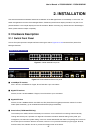
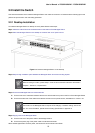
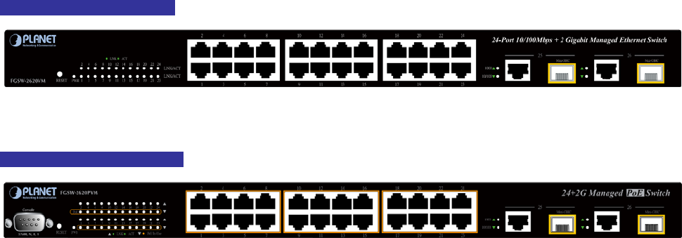
FGSW-2620VM Front Panel
Figure 2-1: FGSW-2620VM front panel
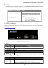
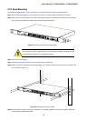
FGSW-2620PVM Front Panel
Figure 2-2: FGSW-2620PVM Switch front panel
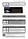
■ 10/100Mbps TP Interface
Port-1~Port-24: 10/100Base-TX Copper, RJ-45 Twist-Pair: Up to 100 meters.
■ Gigabit TP Interface
Port-25, Port-26: 10/100/1000Base-T Copper, RJ-45 Twist-Pair: Up to 100 meters.
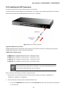
■ Gigabit SFP Slots
Port-25, Port-26: 1000Base-SX/LX mini-GBIC slot, SFP (Small Factor Pluggable) transceiver module: From 550
meters (Multi-mode fiber), up to 10/30/50/70/120 kilometers (Single-mode fiber).
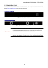
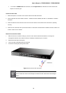
■ Console Port (FGSW-2620PVM Only)
The console port is a DB9, RS-232 male serial port connector. It is an interface for connecting a terminal directly.
Through the console port, it provides rich diagnostic information includes IP Address setting, factory reset, port
management, link status and system setting. Users can use the attached RS-232 cable in the package and connect to
the console port on the device. After the connection, users an run any terminal emulation program (Hyper Terminal,
ProComm Plus, Telix, Winterm and so on) to enter the startup screen of the device.