


User’s Manual of FGSW-2620VM / FGSW-2620PVM
177
8. POWER OVER ETHERNET OVERVIEW
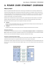
What is PoE?
Based on the global standard IEEE 802.3af, PoE is a technology for wired Ethernet, the most widely installed local area
network technology adopted today. PoE allows the electrical power necessary for the operation of each end-device to be
carried by data cables rather than by separate power cords. New network applications, such as IP Cameras, VoIP Phones,
and Wireless Networking, can help enterprises improve productivity. It minimizes wires that must be used to install the
network for offering lower cost, and less power failures.
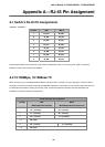
IEEE802.3af also called Data Terminal equipment (DTE) power via Media dependent interface (MDI) is an international
standard to define the transmission for power over Ethernet. The 802.3af is delivering 48V power over RJ-45 wiring.
Besides 802.3af also define two types of source equipment: Mid-Span and End-Span.
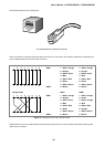
Mid-Span
Mid-Span device is placed between legacy switch and the powered device. Mid-Span is tap the unused wire pairs 4/5
and 7/8 to carry power, the other four is for data transmit.
End-Span
End-Span device is direct connecting with power device. End-Span could also tap the wire 1/2 and 3/6.
PoE System Architecture
The specification of PoE typically requires two devices: the Powered Source Equipment (PSE) and the Powered Device
(PD). The PSE is either an End-Span or a Mid-Span, while the PD is a PoE-enabled terminal, such as IP Phones, Wireless
LAN, etc. Power can be delivered over data pairs or spare pairs of standard CAT-5 cabling.
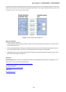
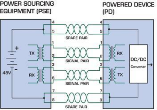
How Power is Transferred Through the Cable
A standard CAT5 Ethernet cable has four twisted pairs, but only two of these are used for 10BASE-T and 100BASE-T. The
specification allows two options for using these cables for power, shown in Figure 2 and Figure 3:
The spare pairs are used. Figure 2 shows the pair on pins 4 and 5 connected together and forming the positive supply, and
the pair on pins 7 and 8 connected and forming the negative supply. (In fact, a late change to the spec allows either polarity
to be used).
Figure 1 - Power Supplied over the Spare Pins