


Philips Semiconductors Product data sheet
SC28L91
3.3 V or 5.0 V Universal Asynchronous
Receiver/Transmitter (UART)
2004 Oct 21
31
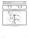
ISR—Interrupt Status Register
This register provides the status of all potential interrupt sources.
The contents of this register are masked by the Interrupt Mask
Register (IMR). If a bit in the ISR is a ‘1’ and the corresponding bit in
the IMR is also a ‘1’, the INTRN output will be asserted (Low). If the
corresponding bit in the IMR is a zero, the state of the bit in the ISR
has no effect on the INTRN output. Note that the IMR does not mask
the reading of the ISR – the true status will be provided regardless
of the contents of the IMR. The contents of this register are
initialized to 0x00’ when the UART is reset.
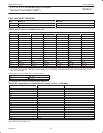
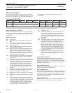
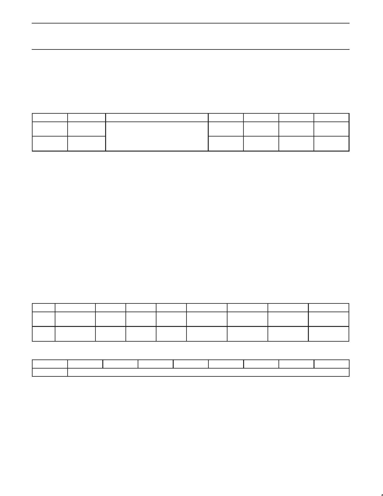
ISR Interrupt Status Register
Addr Bit 7 Bits[6:4] BIT 3 BIT 2 BIT 1 BIT 0
ISR INPUT PORT
CHANGE
Ignore in ISR reads.
Reserved for future function
Counter
Ready
Delta
Break
RxRDY/
FFULL
TxRDY
0x05 0 = not active 0 = not active 0 = not active 0 = not active 0 = not active
1 = active 1 = active 1 = active 1 = active 1 = active
ISR[7]—Input Port Change Status
This bit is a ‘1’ when a change–of–state has occurred at the IP0,
IP1, IP2, or IP3 inputs and that event has been selected to cause an
interrupt by the programming of ACR[3:0]. The bit is cleared when
the CPU reads the IPCR.
ISR[6:4]—Not used, Ignore in ISR read.
ISR[3]—Counter Ready.
In the counter mode, this bit is set when the counter reaches
terminal count and is reset when the counter is stopped by a stop
counter command.
In the timer mode, this bit is set once the cycle of the generated
square wave (every other time that the counter/timer reaches zero
count). The bit is reset by a stop counter command. The command,
however, does not stop the counter/timer.
ISR[2]— Change in Break
This bit, when set, indicates that the receiver has detected the
beginning or the end of a received break. It is reset when the CPU
issues a ‘reset break change interrupt’ command.
ISR[1]—Rx Interrupt
This bit indicates that the receiver is interrupting according to the fill
level programmed by the MR0 and MR1 registers. This bit has a
different meaning than the receiver ready/full bit in the status
register.
ISR[0]—Tx Interrupt
This bit indicates that the transmitter is interrupting according to the
interrupt level programmed in the MR0[5:4] bits. This bit has a
different meaning than the TxRDY bit in the status register.
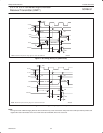
IMR—Interrupt Mask Register
The programming of this register selects which bits in the ISR
causes an interrupt output. If a bit in the ISR is a ‘1’ and the
corresponding bit in the IMR is also a ‘1’ the INTRN output will be
asserted. If the corresponding bit in the IMR is a zero, the state of
the bit in the ISR has no effect on the INTRN output. Note that the
IMR does not mask the programmable interrupt outputs OP3–OP7
or the reading of the ISR.
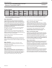
IMR Interrupt Mask Register
Addr Bit 7 BIT 6 BIT 5 BIT 4 BIT 3 BIT 2 BIT 1 BIT 0
IMR INPUT PORT
CHANGE
Reserved Reserved Reserved Counter
Ready
Delta
Break
RxRDY/
FFULL
TxRDY
0x05 0 = not enabled Set to 0 Set to 0 Set to 0 0 = not enabled 0 = not enabled 0 = not enabled 0 = not enabled
1 = enabled 1 = enabled 1 = enabled 1 = enabled 1 = enabled
IVR/GP– Interrupt Vector Register (68k mode) or General–purpose register (80XXX mode)
IVR/GP Bit 7 BIT 6 BIT 5 BIT 4 BIT 3 BIT 2 BIT 1 BIT 0
0x0C Interrupt Vector Register (68XXX mode) or General–purpose register (80XXX mode)
This register stores the Interrupt Vector. It is initialized to 0x0F on
hardware reset and is usually changed from this value during
initialization of the SC28L91 for the 68K Mode. The contents of this
register will be placed on the data bus when IACKN is asserted low
or a read of address 0xC is performed.
When not operating in the 68XXX mode, this register may be used
as a general-purpose one-byte storage register. A convenient use
may the storing a “shadow” of the contents of another SC28L91
register (IMR, for example).