


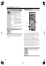
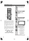

52
First Time Setup
—Continued
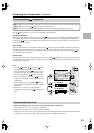
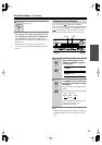
Note:
• This procedure can also be performed on the AV
receiver by using its [SETUP], [ENTER], and arrow
buttons.
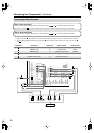
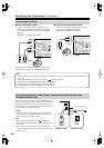
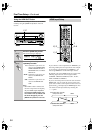
If you connect your TV to the COMPONENT VIDEO
OUT, set the HDMI Monitor setting to No so that the
onscreen setup menus are displayed and composite
video and S-Video sources are upconverted and output
by the COMPONENT VIDEO OUT.
If you connect your TV to the HDMI OUT MAIN or
HDMI OUT SUB, set the HDMI Monitor setting to
Main or Sub, respectively, so that the onscreen setup
menus are displayed and composite video, S-Video, and
component video sources are upconverted and output by
the HDMI OUT MAIN or HDMI OUT SUB.
You can specify the output resolution for the HDMI out-
puts and COMPONENT VIDEO OUT and have the AV
receiver upconvert the picture resolution as necessary to
match the resolution supported by your TV.
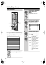
6
Use the Up and Down [ ]/[ ]
buttons to select “Front (Speaker
B),” and use the Left and Right
[ ]/[ ] buttons to select:
NotUse:
Select this if you’re not using
Speakers B.
Normal:
Select this if you’ve con-
nected your front Speakers B
normally.
Bi-Amp:
Select this if you’ve con-
nected your front Speakers B
for bi-amped operation.
BTL:
Select this if you’ve con-
nected your front Speakers B
for bridged operation. The
BTL indicator will appear on
the display.
Note:
• Bi-Amp and BTL cannot be selected
if Front (Speaker A) is set to Bi-Amp
or BTL.
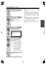
7
Press the [SETUP] button.
Setup closes.
ENTER
S
E
T
U
P
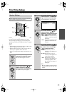
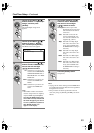
HDMI Monitor Setup
1
Press the [RECEIVER] button,
followed by the [SETUP] button.
The main menu appears onscreen.
INPUT SELECTOR
LISTENING MODE
ON STANDBY
DISPLAY MUTING
G
U
I
D
E
E
X
I
T
PREV
CH
DIMMER
CDR/MD/DOCK
SAT
TAPE/AMP
SLEEP
MACRO
REMOTE MODE
SUBTITLE
AUDIO
REPEAT
PLAY MODE
--
/
---
10 11 12
TV
TV CH
TV VOL
PLAYLIST
RANDOM
DVD
AUX1 AUX
2
GAME/TV
CBL/SATVCR/DVR
D. TUN
CD
TUNER
TAPE
PHONO
REC
ENTER
SURR
DIRECT
THX
PURE A
STEREO
ALL ST
T
O
P
M
E
N
U
M
E
N
U
VOL
CH
DISC
ALBUM
TV
VCR
CABLE
NET/USB
DVD
RECEIVER
CD
+
-
123
ZONE
3
ZONE
2
INPUT
+
-
+10
0
CLEAR
123
456
789
S
E
T
U
P
R
E
T
U
R
N
NET/USB
SP A SP B
2, 3
2–5
1
1, 6
RECEIVER
S
E
T
U
P