


67
Enjoying Movies and Music in the Remote Zone (Zone 2/3)—Continued
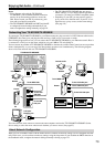
When Connecting the Power Amplifier (Zone 2
or Zone 3)
• You can enjoy a different source in a remote zone
while a 7.1 channel source is being played in the
main room.
• Adjust the volume level on the TX-NR1000/
TX-NR5000E (not on the power amplifier).
• The sleep timer in the main room also works in Zone
2 and Zone 3. To make the sleep timer effective only
in Zone 2 or Zone 3, set the sleep timer on the
TX-NR1000/TX-NR5000E in the main room, and
then put it into the standby status.
• When “Speaker B Surr Back” is set to “Powered
Zone 2” on the Speaker Configuration sub-menu of
the Speaker/Output Setup menu, 7.1 channel play-
back is disabled in the main room.
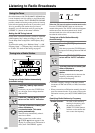
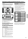
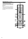
• Sounds and pictures that can be output to Zone 2 and
Zone 3 are as follows:
*1 Only PCM output
*2 Possible for 2 channel downmix signal.
Columns covered by “ \ ” indicate that no setting related
to the column is specified for Zone 2 Out or Zone 3 Out
in “Audio Output Assign” or “Video Output Assign.”
1
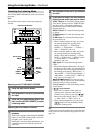
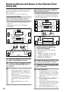
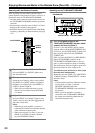
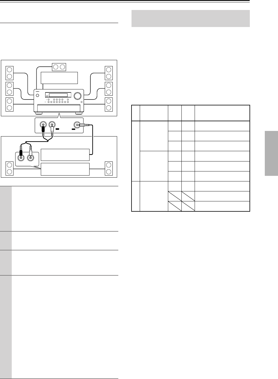
Connect the power amplifier for Zone 2 or
Zone 3 to the TX-NR1000/TX-NR5000E.
Connect to any of the following terminals:
• AUDIO OUT 1-5
• DIGITAL OUT OPTICAL 1-2
• DIGITAL OUT COAXIAL 1-2
2
Connect the speakers for Zone 2 or Zone
3 to the power amplifier.
3
Connect the video component for Zone 2
or Zone 3 to any of the composite VIDEO
OUT 1-4 terminals.
4
Set the Setup menu.
1. On the Setup menu (See page 91), select
“Speaker/Output Setup” → “Audio Output
Assign,” and set the terminal to which the
component is connected to “Zone 2 Out” or
“Zone 3 Out.”
2. Then, set “Zone 2 Out” or “Zone 3 Out” in
the Audio Output Assign sub-menu to “Pre
Out (variable).”
3. Similarly, select “Speaker/Output Setup” →
“Video Output Assign,” and set the terminal
to which the component is connected to
“Zone 2 Out” or “Zone 3 Out.”
4. Press the [SETUP] button to close the
menu.
R
L
IN
OUT
LR
VIDEO
OUT
Main Room
Power amp
Zone 2/Zone 3
TV
TX-NR1000/TX-NR5000E
TV
Enjoying Movies and Music in a
Remote Zone
From Input
Terminal
ZONE
2
REC/
ZONE
3
To Output Terminal
Audio Input
ETHERNET,
PH,
AUDIO IN 1-9
✔✔AUDIO OUT 1-5
DIGITAL OUT OPTICAL 1-2
DIGITAL OUT COAXIAL 1-2
DIGITAL IN
OPTICAL 1-6,
DIGITAL IN
COAXIAL 1-6
✔
*2
✔
*1
AUDIO OUT 1-5
✔✔DIGITAL OUT OPTICAL 1-2
✔✔DIGITAL OUT COAXIAL 1-2
Video Input
VIDEO IN 1-6,
S VIDEO IN 1-
6, COMPO-
NENT VIDEO
IN 1-6
✔✔VIDEO OUT 1-4
S VIDEO OUT 1-4
COMPONENT VIDEO OUT